


Power supply installation Standard 1.07
56 CallPilot
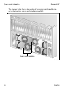
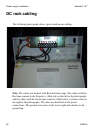
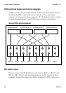
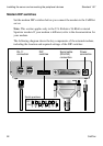
PDU terminal blocks and wiring diagram
A PDU consists of eight terminal blocks within a metal enclosure. Before
installing the PDU, connect the terminal blocks so that each output
connector receives power from a separate -48 V dc branch circuit, as shown
in the following diagram. Use AWG 10 wires for these connections.
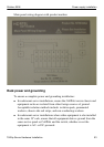
Single PDU wiring diagram
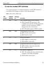
DC power input
DC power input into the distribution unit connects BAT-1 to BAT-4 and
BR-1 to BR-4. Refer to the preceding diagrams for the location of these
terminals. Connect the input wires before installing the PDU on the rack.
G101741
Output server 4 Output server 3 Output server 2 Output server 1
BAT-4 BAT-3 BAT-2 BAT-1 BR-4 BR-3 BR-2 BR-1