


October 2006 1002rp server description
1002rp Server Hardware Installation 21
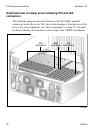
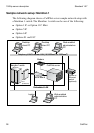
Slot assignments
Introduction
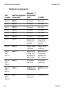
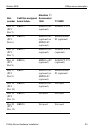
The slot assignment tables show the following:
the physical location of boards inside the server, relative to other boards
the order in which boards are installed (for example, board #1, 2, 3)
how the boards are represented in some CallPilot Manager applications
(such as the Maintenance Administration page)
the maximum capacity for each switch connectivity
Note: Your server can vary depending on what was ordered from Nortel.
Therefore, your server may not have all of the slots populated.
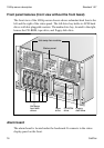
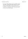
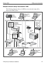
Slot definition and slot numbering
In these tables, the term slot refers to the available slot openings in the
chassis, not the PCI or ISA connectors inside the server.
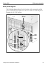
Look at the server from the rear (see “Rear panel diagram” on page 19). The
slots are numbered from right to left, 1 to 20. Now, look at the server from
the front. The slots are numbered from left to right.
Note: For Meridian 1 and Succession 1000, the first MPB16-4 board must
be installed in slot 11. You can install up to a maximum of two MPB16-4
boards.