


October 2006 Power supply installation
1002rp Server Hardware Installation 57
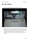
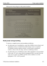
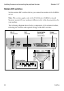
Bringing power and ground into the PDU
Introduction
Install BAT/BATRTN wires in pairs. Each pair of wires supplies voltages to
a module through a power harness. The module harnesses are installed in the
cabinet PDU and connected to the modules at the factory. See “About the
power distribution unit” on page 55.
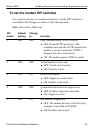
To bring DC power and ground into the PDU
1 If you are using a conduit, terminate the 32 mm (1-1/4 in.) or 19 mm (3/4
in.) conduit at the top rear of the cabinet or at the bottom front of the
cabinet using the knockouts provided. The number of wire pairs you can
run in each conduit depends on the wire gauge.
Note: To preserve ground integrity, the conduit must be insulated.
2 Select a power feed with a circuit breaker dedicated to each module, and
identify it with an appropriate tag.
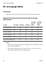
3 Select a wire size to suit the required feed length from the power source
(see “DC wire gauge tables” on page 50).
4 Use pliers to strip 6 mm (1/4 in.) to 13 mm (1/2 in.) of the insulation from
one end of all power and ground feed wires.
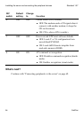
5 Undo the terminal block screws at (-) positions 0, 1, 2, and 3.
6 Insert the red wires into terminal block positions 0, 1, 2, and 3.
7 Secure the wires in the terminal block by tightening the screws.
8 Undo the terminal block screws at (+) positions 0, 1, 2, and 3.
9 Insert the black wires into terminal block positions 0, 1, 2, and 3.
10 Secure the wires in the terminal block by tightening the screws.
11 Select a #10 AWG green wire safety ground and attach it to the cabinet.
12 Measure the module ground continuity by touching one multimeter lead
to any BATRTN terminal block connector and the other end to the GND
terminal block connector. Ensure the measurement is between 0–0.5
ohms.