


October 2006 Installing the server and connecting the peripheral devices
1002rp Server Hardware Installation 65
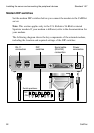
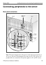
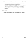
Connecting peripherals to the server
Rear panel connectors
Note: The above diagram shows the power switch and power input for an
AC server. The rest of the diagram is the same for AC or DC servers. For
peripheral device connections, this picture applies to AC and DC servers.
G101648
Power
switch
Power
input
Slot 20
SBC card
(slot 8) Slot 1
SBC
card
COM2
CLAN
connector
PS/2
Keyboard/
Mouse
Monitor
connector
Parallel
port
ELAN
connector
COM1