


Chapter 1 Cables and power 23
Nortel VPN Router Installation — VPN Router 1750
For information about the connectors and cable pinouts, see Appendix A,
“Technical specifications,” on page 69.
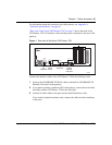
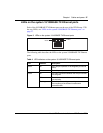
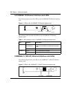
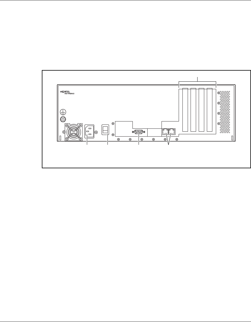
“Rear view of the Nortel VPN Router 1750” on page 23 shows the back of the
VPN Router 1750. All interface cables and the power cord attach to the rear of the
gateway.
Figure 1 Rear view of the Nortel VPN Router 1750
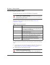
Connect the interface cables to the VPN Router 1750 in the following order:
1 Connect the 10/100BASE-TX RJ-45 cables to the built-in 10/100BASE-TX
Ethernet LAN ports on the gateway.
2 If you plan to connect a terminal or PC to the gateway, connect the serial cable
that ships with the VPN Router 1750 to the serial port.
3 Connect all other cables to the ports on the installed interface cards.
If you ordered optional interface cards, connect the cables for these interfaces
to the ports.
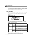
Serial Port
LAN0 LAN1
100 - 240 V~
5 - 3 A
60 - 50 Hz
Power
VPN Router 1750
1234
11424EA
4 PCI slots
10/100
Ethernet
LAN ports
Serial portAC
receptacle
Power
switch