


90 Appendix A Technical specifications
NN46110-316 03.01
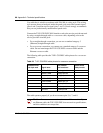
Use cable that is wired in accordance with EIA-568-A wiring style. This wiring
style ensures that a twisted pair inside the patch cord carries the transmit signal
(pins 4 and 5) and the receive signal (pins 1 and 2). nortel strongly recommends
that you use professionally manufactured patch cords.
Connect the quad T1/E1 CSU/DSU WAN interface card to the service provider
network using a straight-through cable or a crossover cable, depending on how the
service provider wired the jack:
• For a straight-through connection, you can use a standard category 5
(Ethernet) straight-through cable.
• For a crossover connection, you cannot use a standard category 5 crossover
cable. Do not interchange the T1/E1 CSU/DSU crossover cable and the
Ethernet crossover cable.
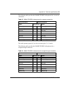
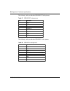
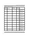
For information about the cable pinouts for a crossover connection, see “T1/E1
CSU/DSU cable pinouts for crossover connection” on page 88. For information
about the cable pinouts for a straight-through connection, see “T1/E1 CSU/DSU
cable pinouts for straight-through connection” on page 89.
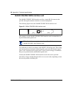
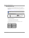
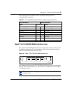
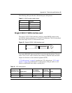
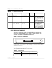
V.90 modem interface card
The V.90 modem interface card has two RJ-11 connectors that provide the signals
to interface to an incoming telephone line and to telephone equipment. The
following figure shows the V.90 modem interface card.
Figure 32 V.90 modem interface card
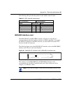
Included in the accessory box is a 7-foot RJ-11 cable to attach to a telephone jack.
PHONE
LINE