


Appendix A Technical specifications 93
Nortel VPN Router Installation — VPN Router 1750
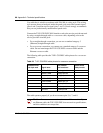
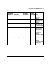
26 M0<-SIGNAL GROUND Pair 12B B Wires 12B, 13A, and
14B connect to pin B
in the 34-pin
connector.
27 M1<-SIGNAL GROUND Pair 13A B Wires 12B, 13A, and
14B connect to pin B
in the 34-pin
connector.
28 M2 Pair 13B No conn The term No conn
means the wire does
not connect to a pin in
the 34-pin connector.
1 SHIELD Pair 14A A At each end, the cable
shield and connector
shell must connect
respectively to pin A of
the 34-pin connector
and pin 1 of the
standard 28-pin
connector.
Do not connect Shield
to Signal Ground
because these are
separate signals.
7 SIGNAL GROUND Pair 14B B Wires 12B, 13A, and
14B connect to pin B
in the 34-pin
connector.
Do not connect Shield
to Signal Ground
because these are
separate signals.
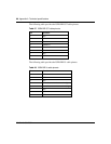
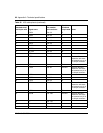
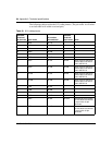
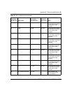
Table 32 V.35 cable pinouts (continued)
Standard-wired
end 28-pin male Signal name
Pair number
and conductor
Special-
wired end
34-pin male Notes