


88 Appendix A Technical specifications
NN46110-316 03.01
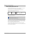
Use cable that is wired in accordance with EIA-568-A wiring style. This wiring
style ensures that a twisted pair inside the patch cord carries the transmit signal
(pins 4 and 5) and the receive signal (pins 1 and 2). Nortel strongly recommends
that you use professionally manufactured patch cords.
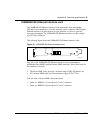
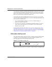
Connect the T1/E1 CSU/DSU WAN interface card to the service provider network
by using a straight-through cable or a crossover cable, depending on how the
service provider wired the jack:
• For a straight-through connection, you can use a standard category 5
(Ethernet) straight-through cable.
• For a crossover connection, you cannot use a standard category 5 crossover
cable. Do not interchange the T1/E1 CSU/DSU crossover cable and the
Ethernet crossover cable.
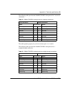
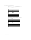
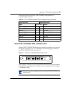
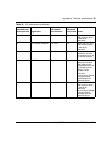
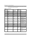
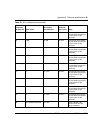
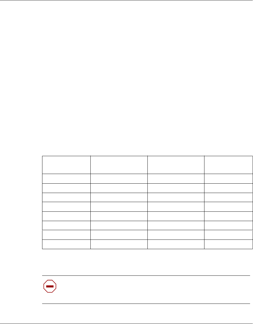
The following table provides the T1/E1 CSU/DSU cable pinouts for a crossover
connection.
The cable operates properly if you do not connect pins 3, 6, 7, and 8.
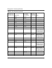
Table 29 T1/E1 CSU/DSU cable pinouts for crossover connection
Standard-wired
end 8-pin male Signal name
Pair number
and conductor
Special-wired
end 8-pin male
1 RXDA<-TXDA wht/org pair 2A 5
2 RXDB<-TXDB orange pair 2B 4
3 Not used wht/grn pair 3A 3
4 TXDB->RXDB blue pair 1B 2
5 TXDA->RXDA wht/blu pair 1A 1
6 Not used green pair 3B 6
7 Not used wht/brn pair 4A 7
8 Not used brown pair 4B 8
Caution: For crossover connections, do not use Ethernet cable. If you
use Ethernet cable, the T1/E1 CSU/DSU does not work to specifications,
and this condition can corrupt data.