


64 Chapter 2 Network configuration
212859-A
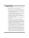
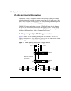
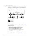
In the above configuration, all of the switch ports are set to participate as VLAN
port members. This arrangement allows the switch to establish the appropriate
broadcast domains within the switch (Figure 20).
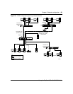
Figure 20 VLAN broadcast domains within the switch
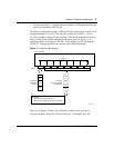
For example, to create a broadcast domain for each VLAN shown in Figure 20,
configure each VLAN with a port membership, and each port with the appropriate
PVID/VLAN association:
• Ports 8, 6, and 11 are untagged members of VLAN 1.
• The PVID/VLAN association for ports 6 and 11 is: PVID = 1.
• Ports 2, 4, 10, and 8 are untagged members of VLAN 2.
• The PVID/VLAN association for ports 2, 4, and 10 is: PVID = 2.
• Ports 2, 4, 10, 8, 6, and 11 are untagged members of VLAN 3.
• The PVID/VLAN association for port 8 is: PVID = 3.
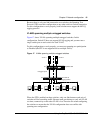
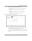
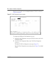
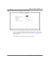
The following steps show how to use the VLAN configuration screens to
configure the VLAN 3 broadcast domain shown in Figure 20.
Port 2
BS45019A
Port 4 Port 10 Port 8
VLAN 3
V2 V2 V2 V1 V2
VLAN 2 VLAN 1
S1
Key
VLAN 1 (PVID = 1)
VLAN 2 (PVID = 2)
VLAN 3 (PVID = 3)
PVID = 2 PVID = 3
V3
PVID = 1
Port 11Port 6