


68 Chapter 2 Network configuration
212859-A
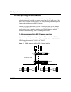
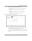
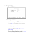
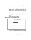
Figure 24 VLAN Port Configuration screen example
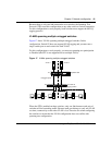
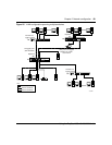
VLAN workgroup summary
This section summarizes the VLAN workgroup examples discussed in the
previous sections of this chapter.
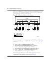
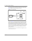
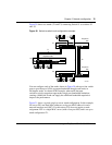
As shown in Figure 25, Switch S1 (BayStack 380 Switch) is configured with
multiple VLANs:
• Ports 1, 6, 11, and 12 are in VLAN 1.
• Ports 2, 3, 4, 7, and 10 are in VLAN 2.
• Port 8 is in VLAN 3.
Because S4 does not support 802.1Q tagging, a single switch port on each switch
must be used for each VLAN (see “VLANS spanning multiple untagged
switches” on page 61).
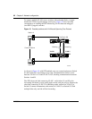
The connection to S2 requires only one link between the switches because S1 and
S2 are both BayStack 380 switches that support 802.1Q tagging (see “VLANs
spanning multiple 802.1Q tagged switches” on page 60).