115
Setting Data Links Section 5-2
4. When using the Controller Link Support Software to set a CJ-series Con-
troller Link Unit, use one of the following methods to set the type of PLC.
• Set the type of PLC to “Others.”
• Add the following information to the device information setting file
(CLKTYPE.TXT) in the Controller Link Support Software to add the
CJ-series PLC and then set the CJ-series PLC.
CJ1G-CPU44: Same settings as the CS1G-CPU44-E
CJ1G-CPU45: Same settings as the CS1G-CPU45-E
For details on editing device information setting files, refer to the Con-
troller Link Support Software Operation Manual (W308).
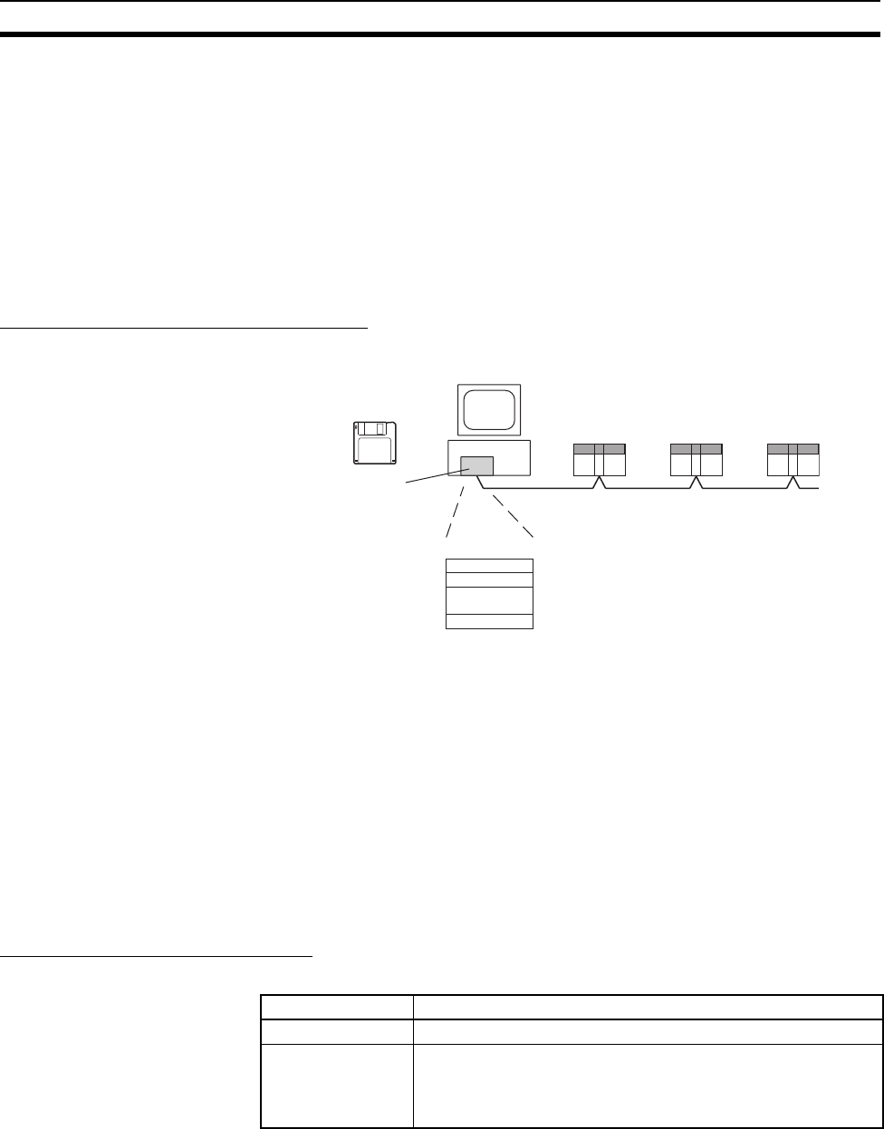
Transferring from a Computer Node
A data link table is created for each node using the Controller Link Support
Software. The data link tables contain all the settings required to create the
data links.
Note 1. The following three methods can be used to start data links. (See p. 153.)
• Using a software switch
• Using the Controller Link Support Software or CX-Net (in CX-Program-
mer)
• Using an FINS command
2. To create data link tables using the Controller Link Support Software, the
network must have been constructed correctly. Set routing tables at each
node as required. See Applications Precautions on page xxii. for details.
Data Link Table Specifications
CS/CJ-series PLCs
Setting data link tables
IBM PC/AT or com
patible computer
Controller Link
Support Board
Controller Link
Support Software
Setting item Setting range
PLC model Set the model of the PLC’s CPU Unit.
Nodes 1 to 32
Set the address of the refresh nodes.
It cannot be set to a parameter exceeding the “maximum node
address” of the network parameter.


