125
Setting Data Links Section 5-2
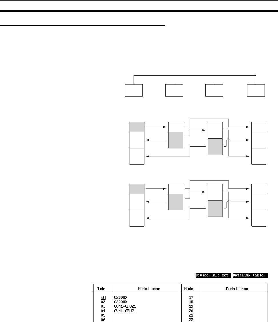
SAMPLE2.CLK: Different Allocations to Each Node
Data links can be created so that one node does not receive from all other
nodes or so that some nodes do not send or receive any data at all. In the fol-
lowing example, node 2 does not receive data from node 3 and node 3 does
not receive data from node 1. Node 4 does not send any add; it only receives
data from other nodes.
Data Link Area Structure
Only nodes in which a data link table has been created can participate in the
data links.
In the data link table, the node sequence can be changed freely; however, the
data link areas must be created consecutively.
Device Information Setting
Data Link Areas
Node 1 Node 2 Node 3
Node 4
C200HX C200HX CVM1-
CPU21
CVM1-
CPU21
Area 1
LR000
LR010
LR030
LR010
LR020
LR039
01000
01020
01039
LR049
01005
01015
01035
01054
Area 2
D00000
D00010
D00030
E0_00020
E0_00030
E0_00049
D00000
D00020
D00039
D00049
E1_00000
E1_00010
E1_00030
E1_00049
#1 #1
#3
#2 #2
#2
#3
#1
#2
#3
#1 #1
#3
#2
#2
#2
#3
#1
#2
#3


