255
Data Link I/O Response Time Section 8-3
Note 1. Use the above equations only if only one Controller Link Unit is mounted
on the PLC. If other CPU Bus Units are mounted on the PLC, obtain the
refresh times for each CPU Bus Unit and add to the above equations.
2. The execution of some items takes precedence over data link area refresh-
ing. For example, data link area refreshing will not take place during exe-
cution of the SEND(192), RECV(193), or FAL(006) instruction.
8-3-3 Calculation Example
The data links of the Controller Link Unit require a slight time delay from the
time the data link area of one node is changed until this change is reflected in
the data link area at another node. This time delay is called the data link I/O
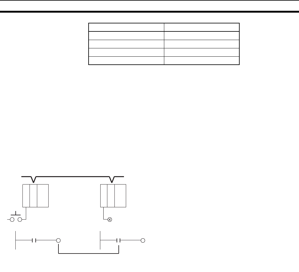
response time. The following is a calculation example of the maximum and
minimum I/O response times for the system configuration shown below.
The data link I/O response time depends on the communications cycle time,
input ON delay, output ON delay, and the cycle times of the PLCs involved.
The values are detailed below.
Communications Cycles
Time
Communications cycle time =
10
× (8 + 16) × 8 + 600 × 4 + 290 × 8 + 320 × 0 + 4 × 0 + 3,290
= 9,930
µs ≅ 9.9 ms
Input ON Delay The input ON delay is the time it takes for an input device to turn ON an input
to the PLC after receiving an input signal. In this system the input ON delay is
1.5 ms.
Output ON Delay The output ON delay is the time it takes for an output device to turn ON an
output signal after receiving an output from the PLC. In this system the output
ON delay is 15 ms.
Cycle Times The cycle time of the PLC at node #1 is 25 ms.
The cycle time of the PLC at node #7 is 10 ms.
PLCs Words per data exchange
CS/CJ-series PLCs Approx. 7,800 words
CVM1 and CV-series PLCs Approx. 3,700 words
C200HX/HG/HE PLCs Approx. 4,000 words
CQM1H-series PLCs Approx. 1,200 words
PLC
PLC
C
L
K
#1
C
L
K
#1
Input
LRXXXX OutputLRXXXX
CLK: Controller Link Unit
System configuration
Baud rate: 2 Mbps
Maximum node address: 32
Number of polled nodes per comm cycle: 4
Number of event-frames per comm cycle: 35
Nodes in network: 8 nodes
Nodes in data links: 8 nodes
Words sent in area 1: 8 words per node
Words in area 2: 16 words per node
No messages communications are performed.
A single Controller Link Unit is mounted to each
CPU Rack.
Input


