362
Memory Areas Appendix B
Communications Unit Flags, Control Bits, and Status Information
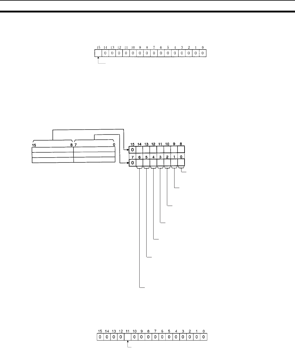
Local Data Link Participation Status: IR 90 (See page 309.)
Data Link Status: IR 91 to IR 93 (See pages 156, 309.)
When the first data link status word is not set or is set to the default (0000) for either the manually set data link
tables or automatically set data link tables, the data link status is stored in the following words for nodes 1 to 6
only.
Terminating Resistance Status: IR 95 (See page 312.)
1: Local node data link participating
0: Local node data link not participating or data link
inactive
Node 2
Node 4
Node 6
PLC status
0: Inactive (user program not running)
1: Active (user program running)
Communications error (data link reception)
0: Normal
1: Error
PLC's CPU Unit error
0: Normal
1: Error
Data link participation
0: Not in data link or data link inactive
1: In data link
Offset error
0: Normal
1: Error
Error: Offset exceeds
number of send words.
Insufficient (short) receive area
0: Sufficient
1: Insufficient
Insufficient: Receive
area is smaller than
send area. Excess data
is truncated; other data
is received.
Remaining receive area
0: Not remaining
1: Remaining
Remaining: Receive
area is larger than send
area. Data is received
and remaining words
are cleared.
Node 1
Node 3
Node 5
IR 91
IR 92
IR 93
Terminating resistance status: 0: OFF
1: ON


