207
Commands and Responses for Controller Link Units Section 6-5
Data link data error counter (response): The total number of data link data
reception errors occurring at all nodes is returned as a total count from the
time the power was turned on. It is expressed, in hexadecimal, as one byte
per node. The count can range from 0 to 255 (i.e., 0 to FF in hexadecimal).
When CS1W-CLK21-V1 and CJ1W-CLK21-V1 Units are used and the Wired
Network 62 Node Enable Bit in the DM Parameter Area software switches is
ON, the data link error counter of nodes 33 to 62 is returned in bytes 33
through 62. In other models, the areas corresponding to nodes 33 to 62 are
reserved for system use.
6-5-7 DATA LINK STATUS READ
Reads the data link operational status.
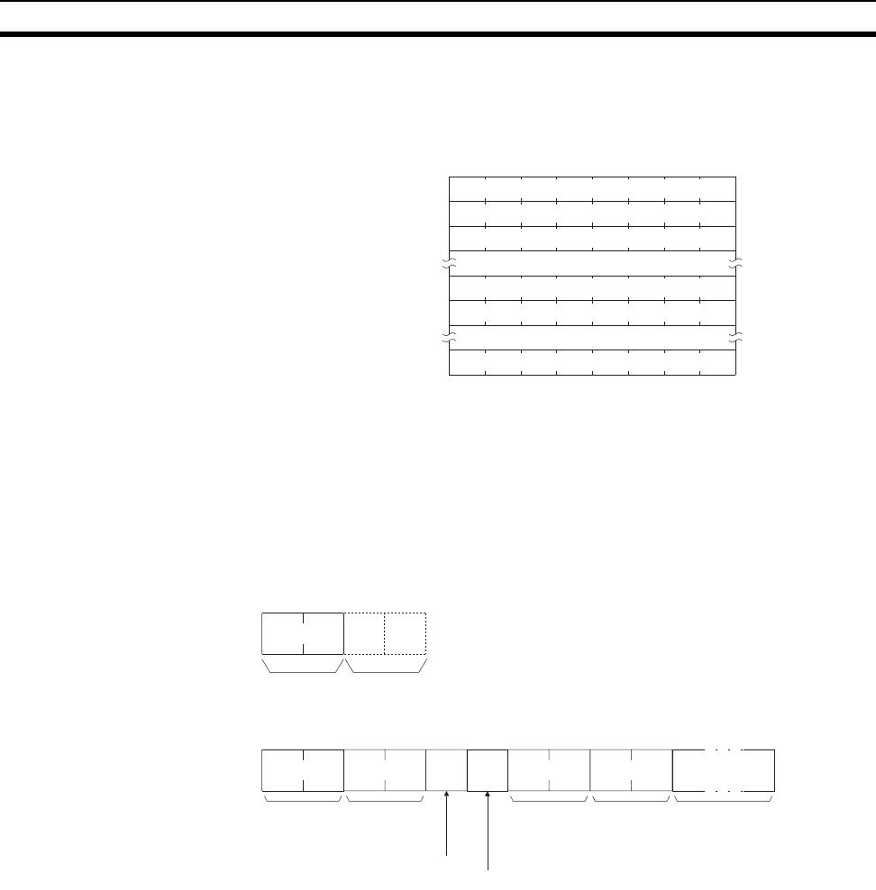
Command Block
Response Block
Note If the type is set to 0000 Hex (or is omitted), only 32 bytes will be returned.
Parameters Type (Command): The number of nodes reading the data link status is spec-
ified as a 2-byte (4-digit) hexadecimal number as follows:
0000 Hex: 32 nodes
0001 Hex: 62 nodes
Default value: 32 nodes
Reading of the data link status for 62 nodes is enabled only when the Wired
Network 62 Node Enable Bit in the DM Parameter Area software switches of
CS1W-CLK21-V1 and CJ1W-CLK21-V1 Units is ON.
7 6 5 4 3 2 1 0
Bit
Byte 1
Byte 2
Byte 3
Byte 32
Byte 33
Byte 62
Number of error occurrences for node #1
Number of error occurrences for node #2
Number of error occurrences for node #3
Number of error occurrences for node #32
Number of error occurrences for node #33
Number of error occurrences for node #62
Command
code
03
06
Typ e
Response
code
Command
code
Status flag
Data link mode
Refresh
cycle time
present
value
Refresh
cycle time
maximum
value
Status
06 03
62 bytes
(See note.)


