


2-13510-A2-GN32-50 January 1998
Principles of Operation
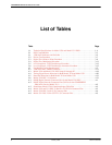
Network Configurations 2-1. . . . . . . . . . . . . . . . . . . . . . . . . . . . . . . . . . . . . . . . . . . . . . . . . . . . . . . . . . . . . .
Point-to-Point 2-1. . . . . . . . . . . . . . . . . . . . . . . . . . . . . . . . . . . . . . . . . . . . . . . . . . . . . . . . . . . . . . . . . . . .
Multipoint 2-1. . . . . . . . . . . . . . . . . . . . . . . . . . . . . . . . . . . . . . . . . . . . . . . . . . . . . . . . . . . . . . . . . . . . . .
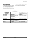
DSU Compatibility 2-3. . . . . . . . . . . . . . . . . . . . . . . . . . . . . . . . . . . . . . . . . . . . . . . . . . . . . . . . . . . . . . . . . .
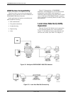
2600 Series Compatibility 2-4. . . . . . . . . . . . . . . . . . . . . . . . . . . . . . . . . . . . . . . . . . . . . . . . . . . . . . . . . . . . .
Local Area Data Set (LADS) Operation 2-4. . . . . . . . . . . . . . . . . . . . . . . . . . . . . . . . . . . . . . . . . . . . . . . . . .
Network Configurations
Connections between 3500 Series DSUs or between
3500 Series DSUs and compatible DCEs are configured in
either of two ways: point-to-point or multipoint.
Point-to-Point
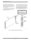
In a point-to-point configuration (Figure 2-1), there is
one DSU at each end of the digital facility. The local
DSU, and likewise the remote, may be a 3500 Series unit
or one of the other devices listed in the DSU
Compatibility section.
The primary channel characteristics of these DSUs are
identical to 2500 Series and 2600 Series DATAPHONE II
DSUs and Paradyne Model 3056 and 3456 DSUs;
therefore, you can configure these devices for installation
at either end of a network containing any compatible
DSU, such as Paradyne Model 3056 units.
Multipoint
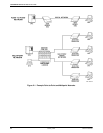
In a multipoint configuration (Figure 2-1), a control
DSU is connected to multiple tributaries communicating
at the same speed on a single digital facility.
For multipoint networks, the DSU at the host end of
the circuit is designated as the control; the other DSUs are
designated the tributaries. The control initiates remote
diagnostic commands; the tributary responds to
commands from the control or from its own local front
panel.
A 3500 Series DSU can be used as a control or as a
tributary in non-network managed networks.
Figure 2-1 depicts a basic multipoint network
containing Model 3511 DSUs in a COMSPHERE
3000 Series Carrier at the local end of the network, and a
combination of standalone 2500 Series DATAPHONE II
DSUs and a Model 3510 DSU at the remote end.
For 2600 Series diagnostic multipoint networks, the
Model 3510 DSU can also be installed as a tributary DSU.
In this application, the standalone Model 3510 DSU at the
tributary end is functionally equivalent to a DATAPHONE
II 2600 Series DSU, and no additional support is needed.
2