


COMSPHERE 3500 Series Data Service Units
4-8 January 1998 3510-A2-GN32-50
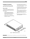
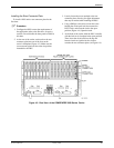
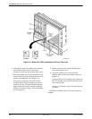
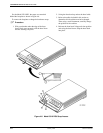
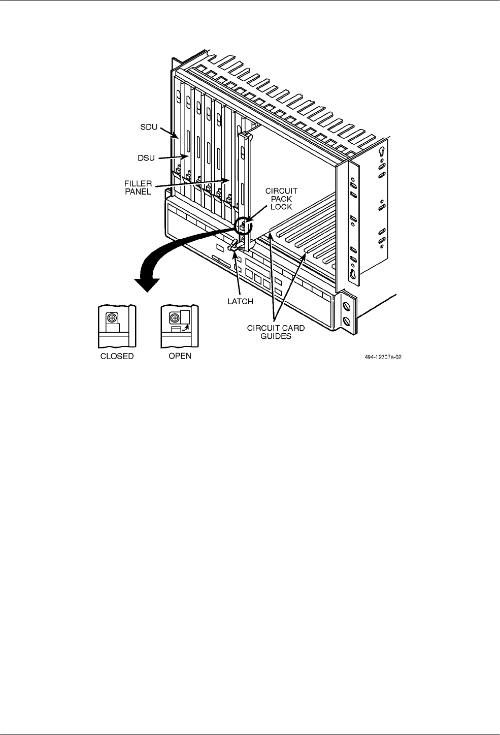
Figure 4-4. Model 3511 DSU Installation and Circuit Pack Lock
6. Aligning the circuit card with the rear connector
plate, slide the DSU into the slot until the
connectors seat firmly into the back of the carrier.
7. Press the faceplate latch to secure the DSU in the
carrier, rotate the circuit pack lock into the closed
position, and tighten the screw (Figure 4-4).
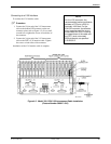
If the carrier is powered, all indicators on the
faceplate flash as the DSU performs an internal
power-on self-test. The green OK indicator then
lights for about 20 seconds, then the red OS/NS
flashes. If no indicators light, verify that the DSU
is receiving power.
8. Return to the rear of the carrier and tighten the
rear connector plate screw.
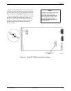
9. At the rear of the carrier, connect the DTE
interface cable onto the rear connector plate (see
Figure 4-3).
If using an EIA-232-D interface cable, connect the
EIA-232-D cable to the top DTE connector on the
rear connector plate.
If using a V.35 interface cable, proceed to the next
procedure.
Installation of the DSU and its rear connector plate is
complete.