


Installation
4-73510-A2-GN32-50 January 1998
Installing the Rear Connector Plate
To install a DSU and its rear connector plate for the
first time:
. Procedure
1. Configure the DSU to meet the requirements of
the application (refer to the Hardware Strapping
section). Do not disable the front panel switches at
this time.
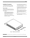
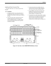
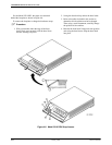
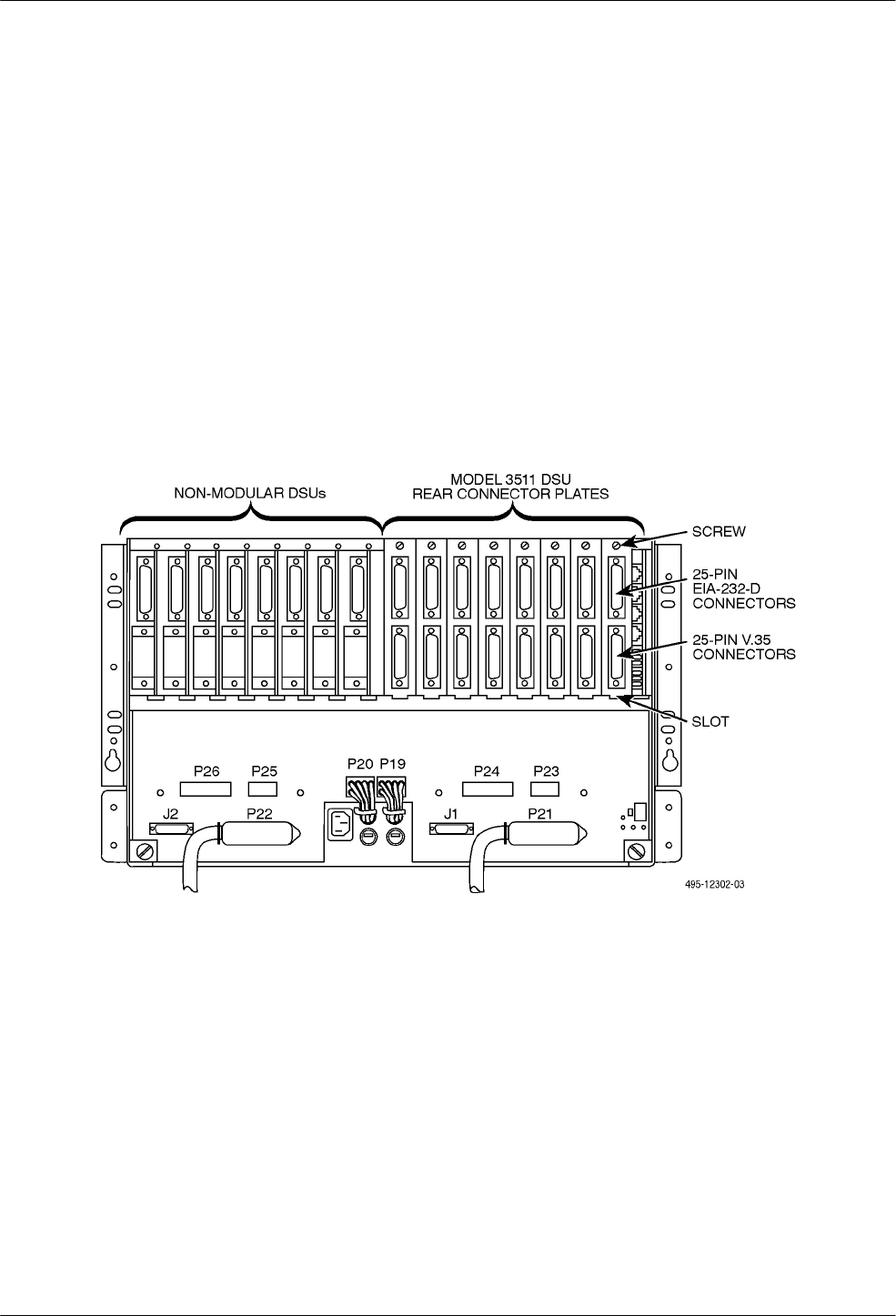
2. At the rear of the carrier, set the tab on the rear
connector plate into one of the slots on the
carrier’s backplane (Figure 4-3). Make sure the
rear connector plate uses the same slot position
intended for the DSU.
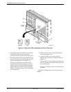
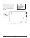
3. Loosely fasten the screw attached to the rear
connector plate, allowing for slight adjustment
that may be needed when installing the DSU.
4. Using a Phillips screwdriver, loosen the screw
holding the circuit pack lock that secures the
DSU’s latch, and rotate the lock to the open
position (Figure 4-4). Open the latch.
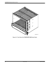
5. At the front of the carrier, hold the DSU vertically
with the latch on its faceplate in the open position.
Then, insert the circuit card into the top and
bottom circuit card guides for the slot that
contains the rear connector plate (see Figure 4-4).
Figure 4-3. Rear View of the COMSPHERE 3000 Series Carrier