


Operation
3-53510-A2-GN32-50 January 1998
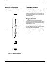
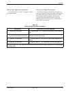
Model 3511 Faceplate
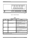
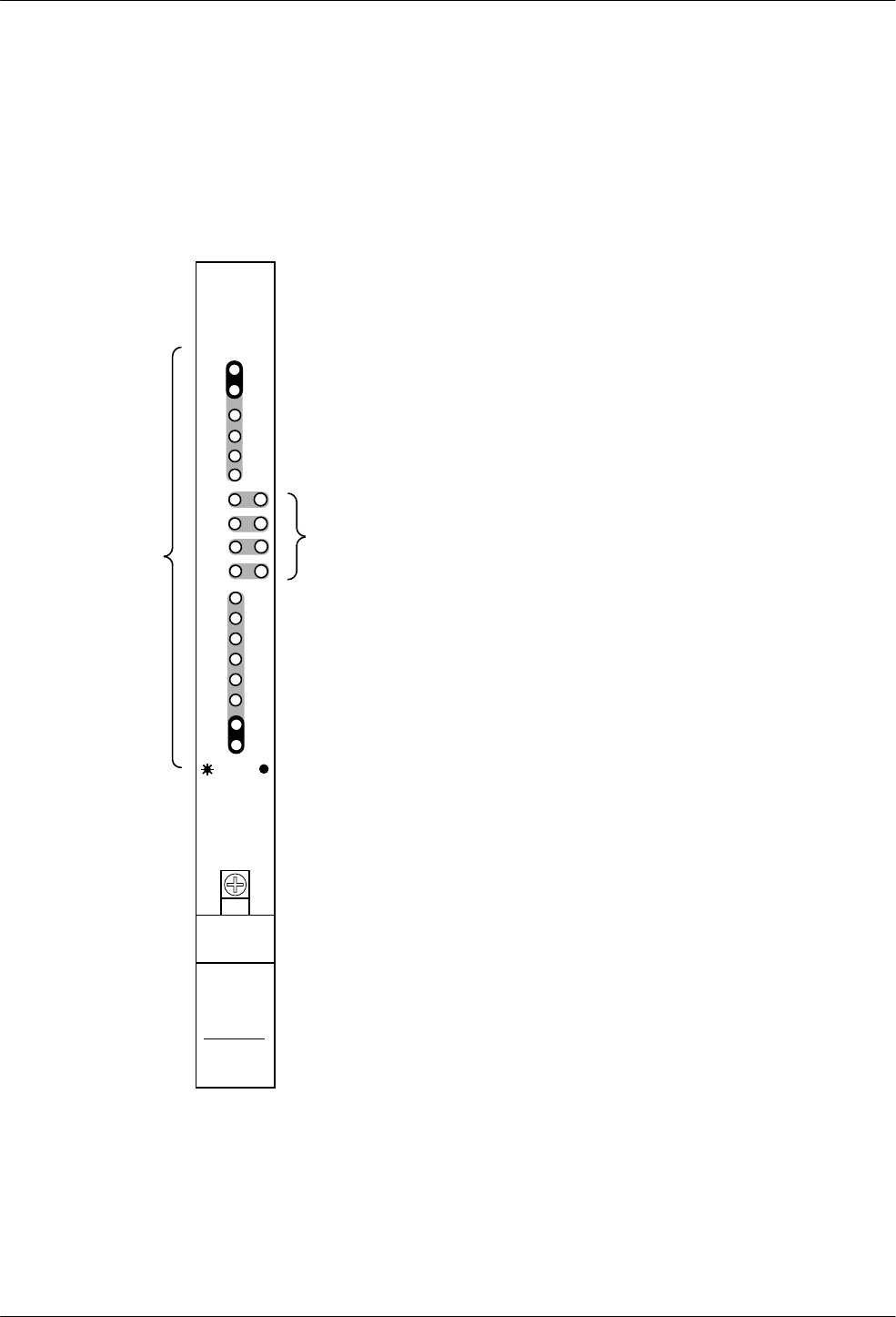
Figure 3-2 shows the Model 3511 faceplate. Indicators
and pushbutton switches for this DSU are listed and
described in Table 3-1.
Test
Rem
Pass
Fail
3511
496-11884-02
Multirate
DSU
Dsbl
TP
LL
DL
RL
OK
NS
9.6
56/64
2.4/4.8
19.2/38.4
SPEED
TXD
RXD
RTS
CTS
DSR
LSD
103
104
105
106
107
109
PUSHBUTTON
SWITCHES
FOR TESTING
LED INDICATORS
OS
Status
Figure 3-2. Model 3511 Faceplate
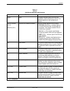
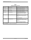
Faceplate Operation
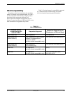
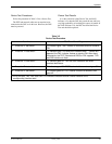
Table 3-1 provides operation descriptions for the eight
DSU status indicators, the four pairs of test switches and
test indicators, and the six DTE interface indicators for
both the 3510 and 3511 DSUs. The status indicators are
always active as long as the DSU is functioning properly
and has power; however, you can choose to disable the
four test switches via a DSU option in order to prevent
unauthorized testing.
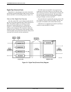
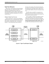
Diagnostic Tests
Use diagnostic tests as part of the installation
procedure to verify proper operation of the DSU, and in
response to service outages to sectionalize the failure to
the DSU, Network, or DTE.
This section describes test procedures to use when all
DSUs on the network are combinations of 3500 or
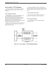
2500 DSUs. Refer to the 2600 DSU Emulation section
when testing 2600/3500 mixed networks.
If the DSU timing straps (S1-1 and S1-2) have been set
to a setting other than DDS, timing may change during
some tests. Appendix B shows these changes.