


3-13510-A2-GN32-50 January 1998
Operation
Overview 3-1. . . . . . . . . . . . . . . . . . . . . . . . . . . . . . . . . . . . . . . . . . . . . . . . . . . . . . . . . . . . . . . . . . . . . . . . . .
Model 3510 Faceplate 3-1. . . . . . . . . . . . . . . . . . . . . . . . . . . . . . . . . . . . . . . . . . . . . . . . . . . . . . . . . . . . . . . .
Model 3511 Faceplate 3-5. . . . . . . . . . . . . . . . . . . . . . . . . . . . . . . . . . . . . . . . . . . . . . . . . . . . . . . . . . . . . . . .
Faceplate Operation 3-5. . . . . . . . . . . . . . . . . . . . . . . . . . . . . . . . . . . . . . . . . . . . . . . . . . . . . . . . . . . . . . . . .
Diagnostic Tests 3-5. . . . . . . . . . . . . . . . . . . . . . . . . . . . . . . . . . . . . . . . . . . . . . . . . . . . . . . . . . . . . . . . . . . .
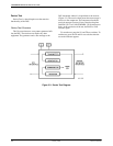
Device Test 3-6. . . . . . . . . . . . . . . . . . . . . . . . . . . . . . . . . . . . . . . . . . . . . . . . . . . . . . . . . . . . . . . . . . . . .
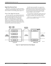
Digital Test (Point-to-Point) 3-8. . . . . . . . . . . . . . . . . . . . . . . . . . . . . . . . . . . . . . . . . . . . . . . . . . . . . . . .
Digital Test (Multipoint) 3-10. . . . . . . . . . . . . . . . . . . . . . . . . . . . . . . . . . . . . . . . . . . . . . . . . . . . . . . . . . .
Local Loopback – DTE Test Message 3-12. . . . . . . . . . . . . . . . . . . . . . . . . . . . . . . . . . . . . . . . . . . . . . . . .
Channel Loopback 3-14. . . . . . . . . . . . . . . . . . . . . . . . . . . . . . . . . . . . . . . . . . . . . . . . . . . . . . . . . . . . . . . .
Troubleshooting 3-14. . . . . . . . . . . . . . . . . . . . . . . . . . . . . . . . . . . . . . . . . . . . . . . . . . . . . . . . . . . . . . . . . . . .
2600 DSU Emulation 3-18. . . . . . . . . . . . . . . . . . . . . . . . . . . . . . . . . . . . . . . . . . . . . . . . . . . . . . . . . . . . . . . .
Disruptive Test and Control Commands 3-18. . . . . . . . . . . . . . . . . . . . . . . . . . . . . . . . . . . . . . . . . . . . . . .
Overview
You can determine operation of the digital network
when it contains 3500 Series DSUs by examining the
DSU’s faceplate status indicators and evaluating the
response to diagnostic tests. These tests are used to isolate
problems when they occur, and to verify that problems
have been successfully corrected.
Use the controls and indicators on the standalone and
carrier-mounted DSUs to operate the units and control the
network. The faceplate on both the Model 3510 and
Model 3511 contains 18 light-emitting diodes (LEDs) and
four pushbutton switches.
The LED indicators light to show the status of certain
diagnostic operating functions, or to indicate the status of
the leads of the DTE interface (TXD through LSD). Use
the four pushbutton switches to run various diagnostic
tests.
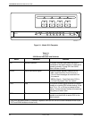
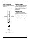
Model 3510 Faceplate
Figure 3-1 shows the 18 indicators and 4 pushbutton
switches on the Model 3510 faceplate. These indicators
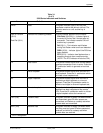
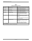
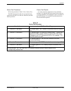
and switches are listed in Table 3-1, and their functions
described.
3