


COMSPHERE 3500 Series Data Service Units
4-20 January 1998 3510-A2-GN32-50
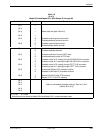
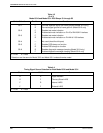
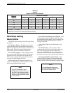
Table 4-3
(3 of 3)
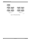
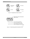
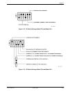
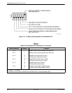
Model 3510 and Model 3511 DSU Straps S1 through S5
Switch Selection Function
1
Position
S5–1
S5–2
S5–3
S5–4
S5–5
S5–6
F
R
F
R
F
R
—
F
R
R
F
Provides separate signal and frame grounds (Model 3510 only)
Connects signal ground to frame ground* (Model 3510 only)
Disables test mode indication
Enables test mode indication on Pin 25 of EIA-232-D interface
Disables test mode indication
Enables test mode indication on Pin NN of V.35 interface
Not used (should be left open)
Disables DSR always on function
Enables DSR always on function
Disables diagnostic message clamping (Model 3510 only)
Enables diagnostic message clamping (Model 3510 only)
F = Front R = Rear
1
Selections are the same for Model 3510 and Model 3511 unless otherwise noted.
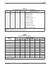
Table 4-4
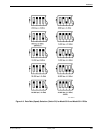
Timing Signal Source Selection for Both Model 3510 and Model 3511
S1–1
S1–2 Source
R
R
F
F
R
F
R
F
Digital Network
Tributary/Slave LADS
Internal LADS
External LADS
F = Front R = Rear