


Installation
4-133510-A2-GN32-50 January 1998
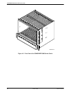
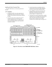
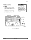
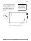
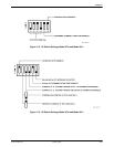
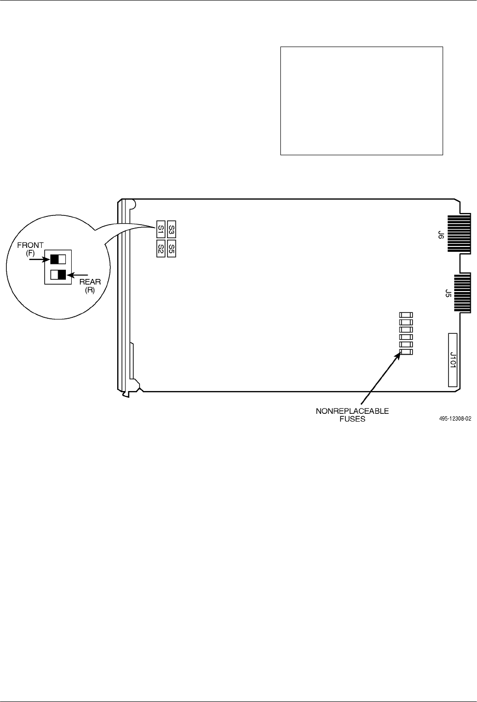
Figure 4-7 shows the physical location of the straps on
a Model 3511 DSU. The straps are not concealed, as they
are on the Model 3510 DSU, and should be set before the
DSU is installed in a COMSPHERE 3000 Series Carrier.
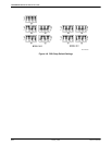
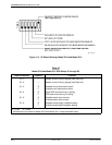
Factory strap settings for both the 3510 and 3511 DSUs
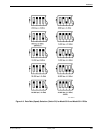
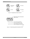
are shown in Figure 4-8 and described in Figures 4-9
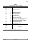
through 4-14. The straps for both models are listed and
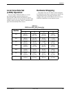
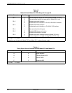
described in Tables 4-3 through 4-5. Table 4-6 lists all
possible network addresses that can be selected by
S4 strap settings.
NOTE
Location of the switch markings
may vary. For clarification,
switches positioned toward the
front of the circuit card (F) are
always Off, while switches
positioned toward the rear (R)
are always ON.
Figure 4-7. Model 3511 DSU Strap and Fuse Locations