


Installation
4-33510-A2-GN32-50 January 1998
Installation Procedures
This section provides instructions for installing
standalone Model 3510 DSUs and carrier-mounted
Model 3511 DSUs. Refer to the appropriate section.
Model 3510 DSUs
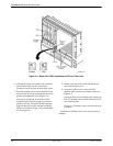
Physical installation of the Model 3510 consists of
unpacking the DSU and placing it in its planned location.
Electrical installation requires the following procedure.
. Procedure
1. Coordinate the installation with the telephone
company and affected digital network user
locations. (Refer to the Government Requirements
section at the front of this manual to ensure
compliance with FCC or Canadian rules.)
2. Configure the DSU to meet the requirements of
the application* (refer to the Hardware Strapping
section later in this chapter).
3. Find a suitable non-switched ac wall outlet
capable of furnishing 90 to 132 Vac, 0.07 amps at
117 Vac. Label the circuit breaker that controls the
outlet and be sure it is set to ON.
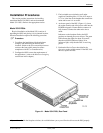
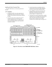
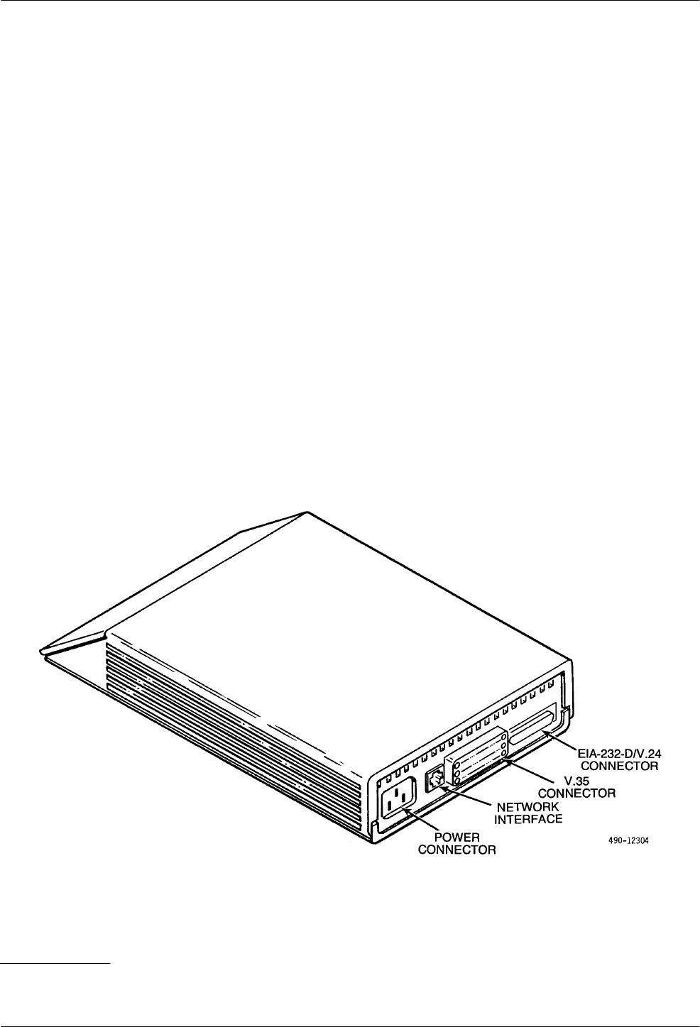
4. At the rear panel of the DSU (Figure 4-1), insert
the socket (female) end of the power cable into the
POWER receptacle. Ensure that the connector is
fully inserted. Connect the other end to the ac
outlet.
Indicators on the faceplate flash as the DSU
performs an internal power-on self-test. The green
OK indicator then lights for about 20 seconds,
then the red OS/NS indicator flashes. If no
indicators light, verify that the DSU is receiving
power.
5. Perform the Device Test as described in the
Operation section of this manual. If the DSU fails
this test, replace the DSU.
Figure 4-1. Model 3510 DSU, Rear Panel
* If you wish to disable the faceplate switches, do not disable them yet or you will not be able to test the DSU properly.