


A-33510-A2-GN32-50 January 1998
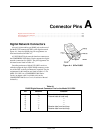
EIA-232-D/V.24 Connector
The Model 3510 DSU’s rear panel and the Model 3511
DSU’s rear connector plate includes a 25-pin
EIA-232-D/V.24 connector for connection to the DTE.
Pin assignments are listed and described in Table A-4.
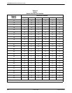
V.35 Connector
The Model 3510 DSU’s rear panel includes a standard
34-Pin V.35 connector. Table A-5 identifies the 34-pin
V.35 interface pin assignments.
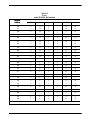
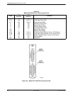
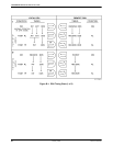
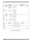
The Model 3511 DSU is shipped with a rear connector
plate, which is mounted onto the rear of the 3000 Series
Carrier. The plate contains two 25-pin DTE connectors, a
25-pin EIA-232-D/V.24 connector and a 25-pin CCITT
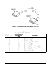
V.35 connector. A V.35 interconnect cable, an interface
between the 25-pin CCITT V.35 connector and a standard
34-pin V.35 connector, is shipped with the rear connector
plate. Figure A-2 shows the rear connector plate and
Figure A-3 shows the V.35 interconnect cable. Table A-6
identifies the interconnect cable’s pin assignments.
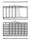
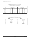
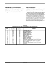
Table A-4
Model 3510 and 3511 DSU 25-Pin EIA-232-D/V.24 Connector Pins
Pins
EIA-232-D
Identifier
CCITT
Identifier
Function
2
3
4
5
6
7
8
9
10
15
17
18
24
25
BA
BB
CA
CB
CC
AB
CF
—
—
DB
DD
LL
DA
TM
103
104
105
106
107
102
109
—
—
114
115
141
113
142
Transmitted Data (TXD)
Received Data (RXD)
Request-to-Send (RTS)
Clear-to-Send (CTS)
Data Set Ready (DSR)
Signal Ground
Line Signal Detect (LSD)
Positive Test Voltage
Negative Test Voltage
Transmitter Signal Element Timing – DCE Source
Receiver Signal Element Timing – DCE Source
Local Loopback
Transmitter Signal Element Timing – DTE Source
Test Mode