


4-13510-A2-GN32-50 January 1998
Installation
Overview 4-1. . . . . . . . . . . . . . . . . . . . . . . . . . . . . . . . . . . . . . . . . . . . . . . . . . . . . . . . . . . . . . . . . . . . . . . . . .
Installation Planning 4-1. . . . . . . . . . . . . . . . . . . . . . . . . . . . . . . . . . . . . . . . . . . . . . . . . . . . . . . . . . . . . . . . .
Model 3510 DSUs 4-1. . . . . . . . . . . . . . . . . . . . . . . . . . . . . . . . . . . . . . . . . . . . . . . . . . . . . . . . . . . . . . . .
Model 3511 DSUs 4-2. . . . . . . . . . . . . . . . . . . . . . . . . . . . . . . . . . . . . . . . . . . . . . . . . . . . . . . . . . . . . . . .
Important Safety Instructions 4-2. . . . . . . . . . . . . . . . . . . . . . . . . . . . . . . . . . . . . . . . . . . . . . . . . . . . . . . . . .
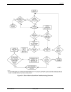
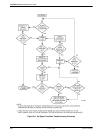
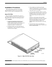
Installation Procedures 4-3. . . . . . . . . . . . . . . . . . . . . . . . . . . . . . . . . . . . . . . . . . . . . . . . . . . . . . . . . . . . . . .
Model 3510 DSUs 4-3. . . . . . . . . . . . . . . . . . . . . . . . . . . . . . . . . . . . . . . . . . . . . . . . . . . . . . . . . . . . . . . .
Removing and Replacing a Model 3510 DSU 4-5. . . . . . . . . . . . . . . . . . . . . . . . . . . . . . . . . . . . . . . .
Model 3511 DSUs 4-5. . . . . . . . . . . . . . . . . . . . . . . . . . . . . . . . . . . . . . . . . . . . . . . . . . . . . . . . . . . . . . . .
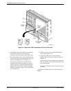
Installing the Rear Connector Plate 4-7. . . . . . . . . . . . . . . . . . . . . . . . . . . . . . . . . . . . . . . . . . . . . . . .
Connecting to a V.35 Interface 4-9. . . . . . . . . . . . . . . . . . . . . . . . . . . . . . . . . . . . . . . . . . . . . . . . . . . .
Connecting to the Digital Network 4-10. . . . . . . . . . . . . . . . . . . . . . . . . . . . . . . . . . . . . . . . . . . . . . . .
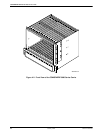
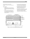
Installing a Model 3511 DSU 4-10. . . . . . . . . . . . . . . . . . . . . . . . . . . . . . . . . . . . . . . . . . . . . . . . . . . . .
Removing a Model 3511 DSU 4-10. . . . . . . . . . . . . . . . . . . . . . . . . . . . . . . . . . . . . . . . . . . . . . . . . . . .
Local Area Data Set (LADS) Operation 4-11. . . . . . . . . . . . . . . . . . . . . . . . . . . . . . . . . . . . . . . . . . . . . . . . . .
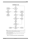
Hardware Strapping 4-11. . . . . . . . . . . . . . . . . . . . . . . . . . . . . . . . . . . . . . . . . . . . . . . . . . . . . . . . . . . . . . . . .
DSU Strap Setting Descriptions 4-24. . . . . . . . . . . . . . . . . . . . . . . . . . . . . . . . . . . . . . . . . . . . . . . . . . . . . . . .
Alarm Output Installation 4-26. . . . . . . . . . . . . . . . . . . . . . . . . . . . . . . . . . . . . . . . . . . . . . . . . . . . . . . . . . . . .
Overview
This chapter contains installation procedures for
configuring and installing the Model 3510 and
Model 3511 DSUs.
Installation Planning
Your installation site should be clean, well-lighted,
well-ventilated, and free from environmental extremes.
Allow 2 to 3 feet of clearance at the front and rear of the
unit for access and cable connections during installation.
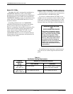
NOTE
DSUs can be operated only at
the data rate for which access to
the digital network is provided by
the telephone company.
NOTE
Before connecting the DSU to
the DDS network, ensure that
approved primary protectors
have been installed on the circuit
in accordance with Article 800 of
the National Electric Code,
NFPA 70, in the United States
and Section 60 of the Canadian
Electric Code, Part 1, in Canada.
Model 3510 DSUs
Model 3510 DSUs must be installed within 6 feet of a
grounded ac outlet controlled by a circuit breaker and
capable of furnishing 90 to 132 Vac, 0.07 amps at
117 Vac. Specific DSU placement depends upon your
requirements.
4