


Installation
4-193510-A2-GN32-50 January 1998
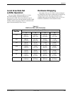
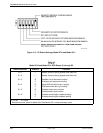
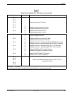
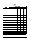
Table 4-3
(2 of 3)
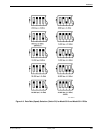
Model 3510 and Model 3511 DSU Straps S1 through S5
Switch Selection Function
1
Position
S2–1
S2–2
S2–3
S2–4
S2–5
S2–6
—
—
—
—
R
F
R
F
Select data rate (see Table 4-5)
Disables streaming terminal function
Enables streaming terminal function
Disables system status function
Enables system status function
S3–1
S3–2
S3–3
S3–4
S3–5
S3–6
F
R
F
R
F
R
F
R
F
R
F
R
Disables faceplate switches
Enables faceplate switches
Enables continuous control of RTS lead
Enables switched control of RTS lead
Disables control of LL testing through EIA-232-D/V.24 connector
Enables control of LL testing through EIA-232-D/V2.4 connector
Disables control of LL testing through CCITT V.35 connector
Enables control of LL testing through CCITT V.35 connector
Enables 64,000 bps CC scrambler function
Disables 64,000 bps CC scrambler function
Selects EIA-232-D/V.24 DTE interface
Selects CCITT V.35 DTE interface
S4–1
S4–2
S4–3
S4–5
S4–6
Refer to the Network Address settings, Table 4-6, S4-4
(Model 3510 only)
F = Front R = Rear
1
Selections are the same for Model 3510 and Model 3511 unless otherwise noted.