


13--5
Powerware 9330 (10 kV A--40 kVA) Installation and Operation
164201300 REV. G 061502
13.4 Hardware Requirements
The following hardware components are required to connect the Remote
Notification function.
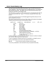
· Modem: Basic external PC modem supporting the following AT commands.
T --- To n e d i a l i ng.
&F --- Load factory defaults.
E0 --- Do not echo characters in command state.
N0 --- Handshake only at speed specified by S37.
Q0 --- Return result codes in both originate and answer mode.
V0 --- Display result codes as numbers.
X0 --- Provide basic result codes: OK (0), CONNECT (1), RING (2),
NO CARRIER (3), and ERROR (4).
&D0 --- Ignore status of DTR signal.
&K0 --- Disable local flow control.
&Q5 --- Communicate in erro r control mode.
S0=1 --- Auto Answering (1 ring).
S37=6--- 2400 Baud.
&W0 --- Store setup in profile O.
&Y0 --- Recall profile O on power up.
NOTE: Consult the modem manufacturer’s manual to confirm that the above
commands are supported by your mo dem.
· Null modem serial cable with a male D B25 connector on the modem end and a
DB9 connector on the UPS end.
All the above items can be acquired at your local computer products supply store.
An alternative to purchasing a cable is to build your own serial cable using the
following pin out description :
DB25 to DB9 Null Modem Interface
Male DB25 Male DB9
pin 2 pin 2
pin 3 pin 3
pin 4 pin 8
pin 5 pin 7
pin 6 pin 1, 4
pin 7 pin 5
pin 8, 20 pin 6