


2-- 27
Powerware 9330 (10 kV A--40 kVA) Installation and Operation
164201300 REV. G 061502
2.4.4 Installing Options Cabinet External Power Wiring
NOTE: Remove Options cabinet input and output conduit landing plate to punch
conduit holes.
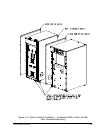
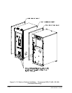
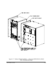
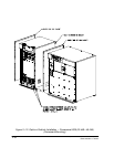
1. Route input and output cables to input/output terminal block. Refer to
Appendix A of this manual for wiring access information.
2. If optional Power Distribution Module (PDM) is installed in the Options cabinet,
proceed to step 10; otherwise, proceed to step 3.
3. If wiring a single feed system, proceed to step 4; if wiring a dual feed system,
proceed to step 6.
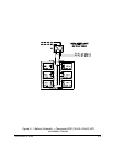
4. Connect phase A, B, C, and Neutral mains and bypass input power wiring from
source to the bypass input terminals in the Options cabinet. Refer to Appendix
A of this manual for wiring and termination requirements and wiring access
information. Note wiring connections for single feed systems.
5. Proceed to step 8.
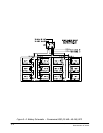
6. Connect phase A, B, and C mains input power wiring from source to the mains
input terminals in the Options cabinet. Refer to Appendix A of this manual for
wiring and termination requirements and wiring access information. Note
wiring connections for dual feed systems.
7. Connect phase A, B, C, and Neutral bypass input power wiring from source to
the bypass input terminals in the Options cabinet. Refer to Appendix A of this
manual for wiring and termination requirements and wiring access information.
Note wiring connections for dual feed systems.
8. Connect phase A, B, and C and Neutral output power wiring from output
terminals to critical load. Refer to Appendix A of this manual for wiring and
termination requirements and wiring access information.
9. Proceed to step 17.
10. If wiring a single feed system, proceed to step 11; if wiring a dual feed system,
proceed to step 13.
11. Connect phase A, B, C, and Neutral mains and bypass input power wiring from
source to the bypass input terminals in the Options cabinet. Refer to Appendix
A of this manual for wiring and termination requirements and wiring access
information. Note wiring connections for single feed systems.
12. Proceed to step 15.
13. Connect phase A, B, and C mains input power wiring from source to the mains
input terminals in the Options cabinet. Refer to Appendix A of this manual for
wiring and termination requirements and wiring access information. Note
wiring connections for dual feed systems.
14. Connect phase A, B, C, and Neutral bypass input power wiring from source to
the bypass input terminals in the Options cabinet. Refer to Appendix A of this
manual for wiring and termination requirements and wiring access information.
Note wiring connections for dual feed systems.