


2-- 13
Powerware 9330 (10 kV A--40 kVA) Installation and Operation
164201300 REV. G 061502
2.3 Battery Cabinet Installation
To install optional battery cabinets, perform the procedures in the following
paragraphs.
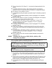
2.3.1 Unloading the Battery Cabinet from the Pallet
To remove the Battery cabinet from the pallet, refer to paragraph 2.2.1.
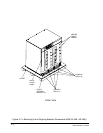
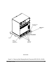
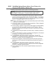
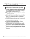
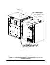
2.3.2 Joining the Battery Cabinet to the UPS Cabinet
To jo in battery cabinets to the UPS, perform the following steps. Refer to
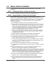
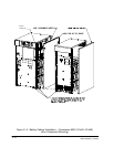
Figure 2---5 for non-permanent installation or Figure 2---6 for permanent installation
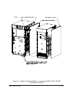
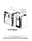
of the Powerware 9330 (10 kVA---20 kVA) UPS and Figure 2---7 for non-permanent
installation or Figure 2---8 for permanent installation of the Powerware 9330
( 25 k VA --- 40 k VA ) U P S .
1. Ro ll the Battery cabinet to a spot near the right side of the UPS.
2. Remove left front solid panel, and right front vented panel from the Powerware
9330 (10 kVA---20 kVA) UPS cabinet or left front solid panel and front vented
panels from Powerware 9330 (25 kVA---40 kVA) UPS cabinet. Front panels are
secured with magnetic latches and are removed by pulling panel s straight
forward to disengage magnetic latches (see Figure 2---1 or 2---3).
3. Remove front vented panel from Battery cabinet. The front panel is secured
with magnetic latches and are removed by pulling panels straight forward to
disengage magnetic latches.
4. Remove right side outside panel from UPS cabinet. Retain hardware.
5. Remove right side panel from Battery cabinet. Retain hardware.
6. Install side panel removed from the Battery cabinet to the right side of the UPS
cabinet. Secure with screws removed from UPS cabinet.
7. Find the battery cable with 2-pole connector in the Battery cabinet. Route this
connector into the UPS cabinet and mate with the matching connector in the
U P S ( s e e F i g ures 2 --- 5 , 2 --- 6 , 2 --- 7 , o r 2 --- 8 ) .
8. Push the Battery cabinet against the right side of the UPS cabinet.
9. If permanently mounting the system, proceed to step 16; otherwise, proceed to
step 10.
10. Secure the Battery cabinet in position by lowering the leveling feet, until
cabinet is not resting on the casters and the cabinet is level.
11. Secure the front of Battery cabinet to the front of the UPS cabinet by sliding the
angle grounding/mounting bracket, from installation kit, behind the base of the
Battery and UPS cabinets with the bottom angle facing outward (see Figures
2---5 or 2---7). Use hardware provided in the kit to secure the bracket.
12. Remove the top side panel mounting screw (tie/grounding bracket location in
Figures 2---5 or 2---7) from both the Battery and UPS cabinets.
13. Secure the back of Battery cabinet to the back of the UPS cabinet with the
tie/grounding bracket. Secure the bracket with the side panel mounting
screws.