


6-- 4
Powerware 9330 (10 kV A--40 kVA) Installation and Operation
164201300 REV. G 061502
6.2.1 Normal Mode
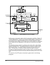
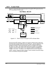
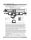
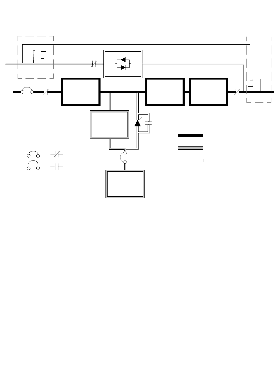
Figure 6---2 shows the path of electrical power through the UPS system when the
UPS is operating in Normal mode.
CB1
CB2
K1
K5
K3
K2
Open
Closed
Breakers
Contactors
Main Power Flow
Energized
De--Energized
Trickle Current
RECTIFIER
STATIC
SWITCH
BOOST
CONVERTER
INVERTER
NORMAL MODE
CHARGER
BATTERY
MAINTENANCE
BYPASS SWITCH
MAINTENANCE
BYPASS SWITCH
Figure 6---2. Path of Current Through the UPS in Normal Mode
During normal UPS operation, power for the system is derived from a utility input
source through the input breaker CB1 and contactor K1. ”Normal” appears on the
front panel and indicates the incoming power is within voltage and frequency
acceptance windows. Three phase AC input power is converted to DC using a
full---wave, six---pulse, solid---state rectifier block which supplies unregulated DC
voltage to a boost converter which in turn supplies a higher and regulated DC
voltage to the inverter. The battery is not charged directly from the unregulated
rectifier. Instead, a separate battery charger is used to maintain the proper charge
level on the battery during normal operation.