8-- 1
Powerware 9330 (10 kV A--40 kVA) Installation and Operation
164201300 REV. G 061502
Using the Control Panel
8.1 Description
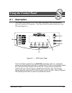
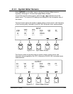
This chapter describes the UPS Control Panel, including controls and indicators,
and how to monitor UPS operation. The Control Panel is located on the front of the
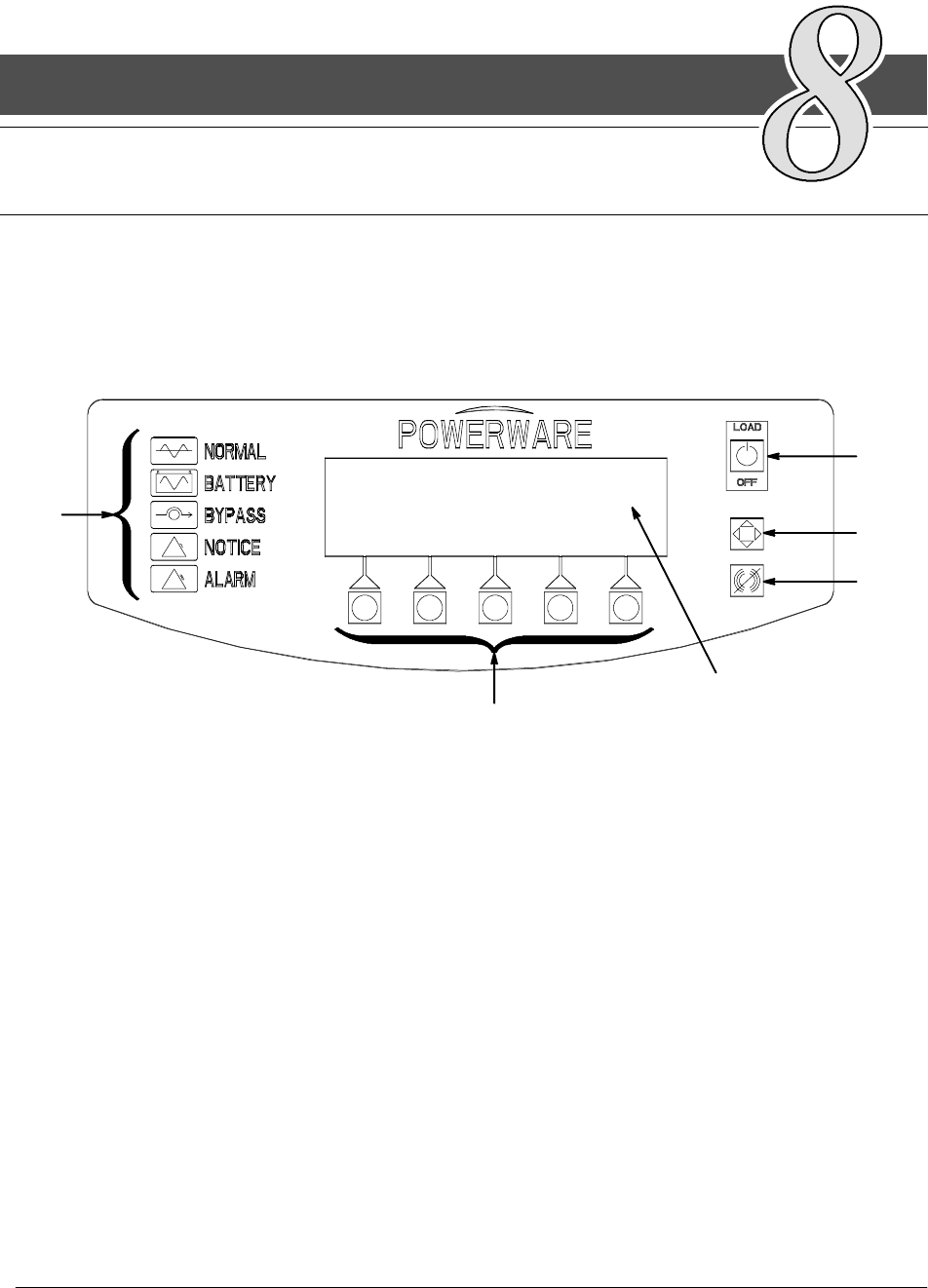
UPS(seeFigure8---1).
1
2
3
4
5
6
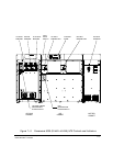
Figure 8 ---1. UPS Control Panel
The Control Panel contains the red LOAD OFF pushbutton switch (1), a dedicated
system control pushbutton switch (2), an audible Alarm Off (horn off) pushbutton switch
(3), a flat Liquid Crystal Display (LCD) screen (4), a horizontal row of pushbutton
switches (5), and a vertical column o f backlit status indicators, (6). The following
sections describe using the UPS Control Panel to monitor the UPS. Refer to Chapter 9
UPS Operating Instructions for use of the operational controls.
8


