


4-- 3
Powerware 9330 (10 kV A--40 kVA) Installation and Operation
164201300 REV. G 061502
Table 4---1. Remote EPO Wire Terminations
From Remote
EPO Switch(s)
To Communications Server
Board TB5 in UPS Cabinet
Remarks
TB1
Use any open
Termina l
T B5 --- 3
Twisted
wires
(
2
)
TB2
Use any open
Termina l
T B5 --- 4
w
i
r
e
s
(
2
)
1 4 --- 1 8
gauge
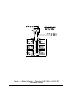
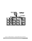
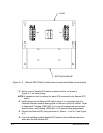
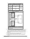
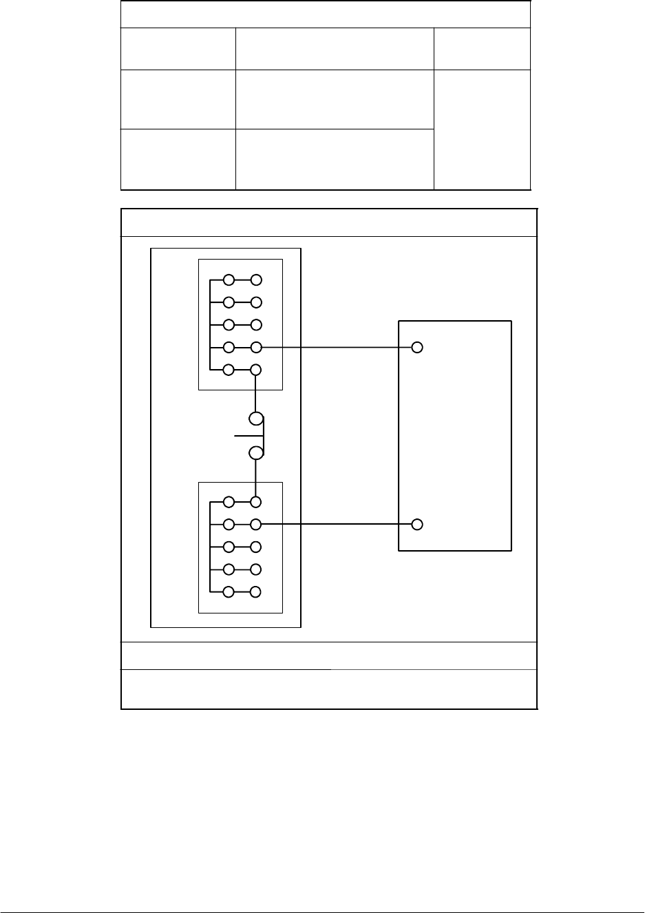
Table 4---2. Remote EPO
3
TB5
4
REMOTE
EPO
SWITCH
TWISTED
WIRES (2)
UPS
(N.C.)
TB1
TB2
Remote EPO switch rating is 24 VDC, 1 Amp minimum.
NOTE: This switch must be a dedicated swi tch not tied into
any other circuits.
7. If required, install ½-in. conduit and wiring from the Remote EPO switch to trip
circuitry of upstream protective devices. A separate contact block, with the
appropriate normally open or normally closed contacts, must be used for this
function. Remote EPO switch wiring must be in accordance with UL Class 1
requirements.
8. When wiring is complete, remove cover from Remote EPO switch enclosure
bottom. Turn cover over and secure to enclosure bottom.
9. Secure the UPS by reversing all steps taken to prepare it for Remote EPO
installation.