


11--1
Powerware 9315 Parallel Capacity/Redundant System with PHP SSBM
164201373 Rev. A 092402
Using Features and Options
11.1 General
The many standard features of your Parallel Capacity/Redundant system Parallel
Capacity/Redundant s ystem provide consistent, economical, and dependable
power protection. In addition, you can add available options to enhance the
performance of your system. This chapter provides descriptions of some of the
features and o ptions introduced earlier in this manual. Refer to drawings
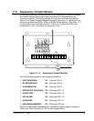
164201373---4 a nd 164201373---13 in Appendix A for location of the customer
interface panel and for terminal wir ing information.
NOTE: Refer to the applicable Powerware 9315 Operation manual provided with
the UPS for UPS features and options
11.2 Building Alarm Monitoring
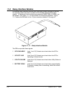
This standard feature lets you connect the S witchboard System Bypass Module
(SSBM) to yo ur building alarms, such as smoke detectors or overtemperature
alarms. The terminals for external connections are located inside the SSBM on the
customer interface panel.
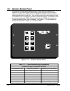
Regardless of how you assign the building alarms, they display as Building Alarm 1,
Building Alarm 2, Building A l arm 3, etc., on the LCD screen o f the Monitor Panel. You
should use t wisted pair wires for each alarm input and common.
If the SSBM is equipped for a Powerware Sync Control, Hot-Tie Control, or
continuous duty static switch, not all Building Alarms will be a vailable for customer
use. See Appendix A, Drawing 164201373---4 for affected areas.
If the SSBM is equipped with an optional System Maintenance Bypass (S MB), not
all Building Alarms will be available for customer use. See Appendix A, Drawing
164201373---4 for affected areas.
11.3 General Purpose Relay C ontacts
Two general purpose relay contacts are provided as a standard feature on the
S SBM. The alarm contacts (one notice and one alarm) are located inside the
SSBM on the customer interface panel. Refer to drawings 164201373---4 and
164201373---13 in Appendix A for location of the customer interface panel and
for terminal wiring information.
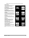
You can specify that each contact be either normally closed (NC) or normally op en
(NO). If the state of thecontact changesfrom the state youspecify as normal, a nsignal
is issued. You can connect these contacts to equipm ent at your facility (such as a light
or an alarm bell) to let you know when an alarm is active on the SSBM. This feature
is useful if the SSBM is located in a remote area where the SSBM alarm horn may not
be heard immediately.
NOTE: In choosing contacts, note that Relay 1 is normally deenergized and is
only ener gized for an alarm condition. Relay 2 is normally energized and is
only d eenergized for an alarm condition.
CAUTION:
Contacts should not be operated in excess of
30 VAC or 42.4V peak AC or DC @ 1A maximum.
11