


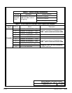
DESCRIPTION:
DRAWING NO: SHEET:
164201373---7
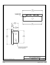
REMOTE EMERGENCY POWER OFF
1of2
A --- 26
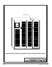
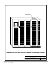
Powerware 9315 Parallel Capacity/Redundant System with PHP SSBM
164201373 Rev. A 092402
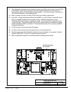
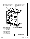
1. The Remote EPO feature shuts down the UPS modules, opens all breakers in the
Switchboard System Bypass Module and isolates power from your critical load. Local
electrical codes may also require t ripping upstream protective devices to the UPS
modules.
2. To open all UPM breakers, a separate twisted pair of wires and an EPO Kit (sold
separately) must be installed to the modules from the SSBM.
3. Use C lass 1 wiring methods (a s defined by the NEC) for control wiring. Install the control
wiring in separate conduit from the power wiring. The wire should be rated at 24 vo l ts,
1 amp minimum.
4. Refer to Table N of this drawing and to applicable chapters for information about installing
control remote EPO.
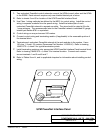
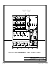
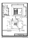
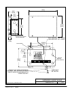
5. Refer to drawings 164201373---4 and 164201373---13 for location of the Customer Interface
panel and drawing 164201373---4 for the terminal block location on the Customer Interface
Panel.
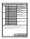
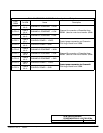
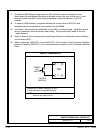
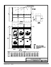
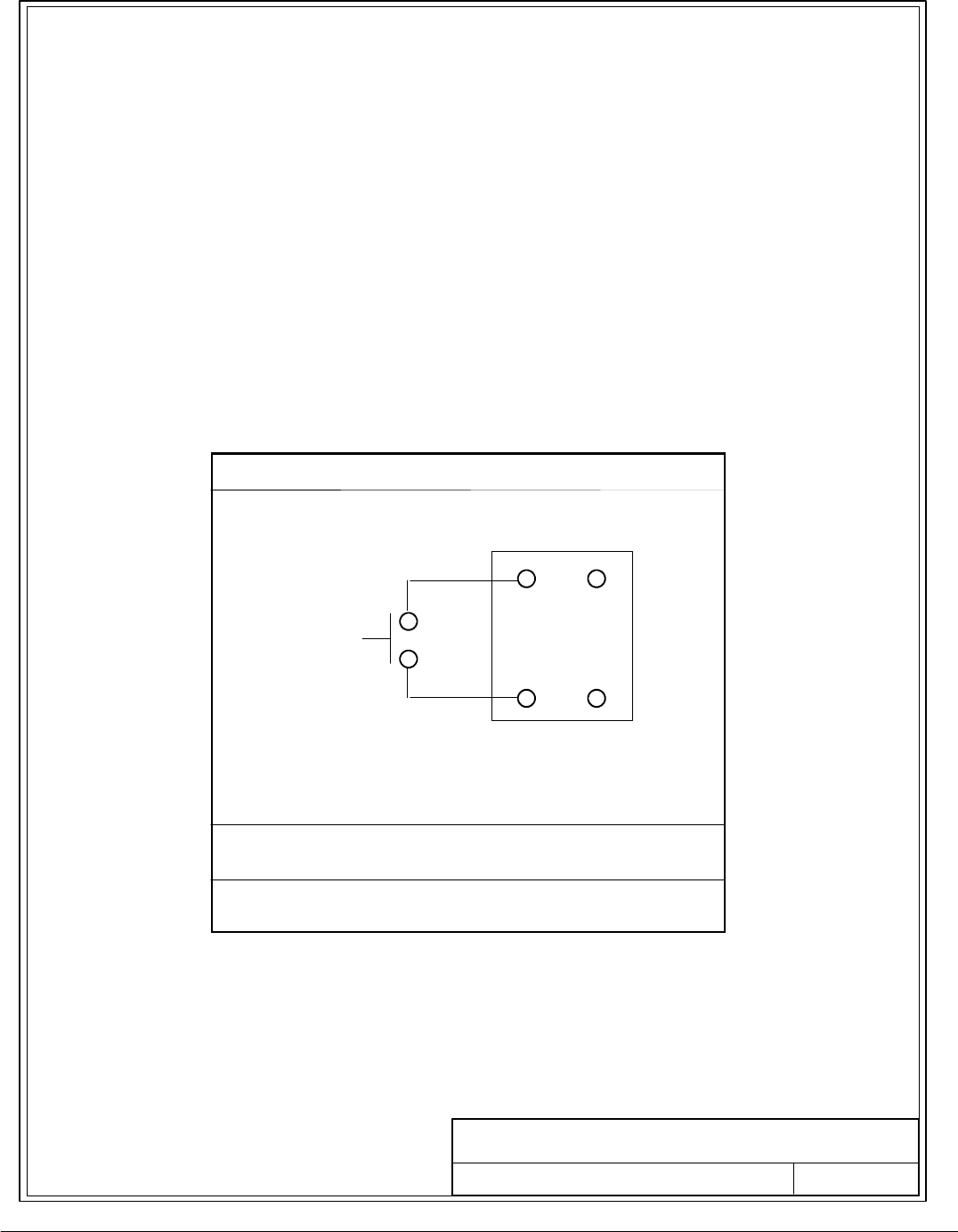
TableN. RemoteEPO
1
2
REMOTE
EPO
SWITCH
TWISTED
WIRES (2)
TB2
Remote EPO switch rating is 24 VDC.
1 amp minimum if supplied by u ser.
NOTE: This switch must be a dedicated switch, and not
tied into any other circuits.