


2-- 3
Powerware 9315 Parallel Capacity/Redundant System with PHP SSBM
164201373 Rev. A 092402
2.3 Installing Optional System Maintenance Bypass (SMB)
The System Maintenance Bypass is shipped as a separate shipping section. The
SMB section is bolted to a wooden pallet.
CAUTION:
The SMB is heavy. If unloading instructions are not followed closely, the
cabinet may tip and cause serious injury or damage. Do not tilt cabinets more
than 10 degrees from vertical.
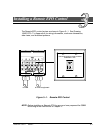
1. Find section label on SMB. Install the SMB in numerical order with SSBM
shipping sections.
CAUTION:
Only insert the forklift jacks where “FORK HERE” signs appear on cabinet
packaging.
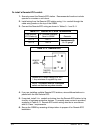
2. Move the SMB to final installed location on t he right side of the SSBM shipping
sections using forklift jacks between the raised supports on the bottom of the
unit.
3. Remove side panel from SMB cabinet to gain a ccess to hardware securing
cabinet to pallet.
4. Remove hardware securing cabinet t o pallet.
CAUTION:
Lift only at lifting eyes or cabinet damage may occur.
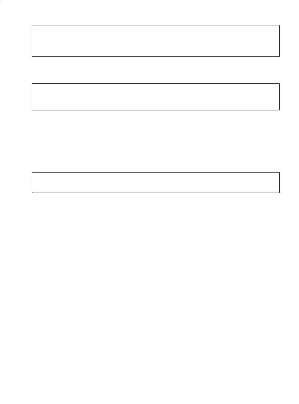
5. Attach s uitable hoist to SMB lifting eyes and lift SMB cabinet until the cabinet
bottom clears t he pallet by a pproximately 3 mm (1/8 in.).
6. Once SMB cabinet is clear of the pallet, pull the pallet from under the UPS
cabinet. Discard o r recycle them in a responsible manner.
7. Carefully lower the SMB cabient until the cabinet base contacts t he floor.
8. Remove lifting eyes from SMB cabient.
9. With t he SMB in its final location, align with SSBM shipping sections.
10. Bolt SMB to SSBM with supplied hardware and anchor to floor or pad.
11. Install all Bypass, C r itical, and Neutral Bus shipping split bus plates. Torque
supplied hardware t o 30 ft-lbs.
12. Install all Ground Bus shipping split bus plates. Tighten supplied hardware.
13. Run SMB wiring ha rnesses through wire trough in rear cabling area and pa ss
into Control section through grommeted opening.
14. Connect Mate-N-Lock plug and cap at t emporary Load Bank current
transformers.
15. Insert harness plugs into matching caps in t he bottom o f the A1 Panel in the
Control Section.