


DESCRIPTION:
DRAWING NO: SHEET:
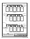
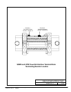
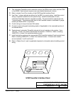
SSB M CUSTOMER INTERFACE PANEL
6of6
164201373---4
A --- 18
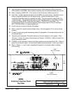
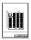
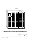
Powerware 9315 Parallel Capacity/Redundant System with PHP SSBM
164201373 Rev. A 092402
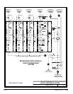
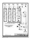
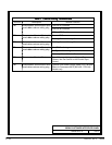
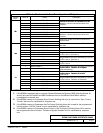
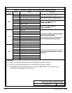
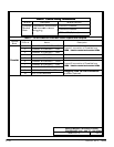
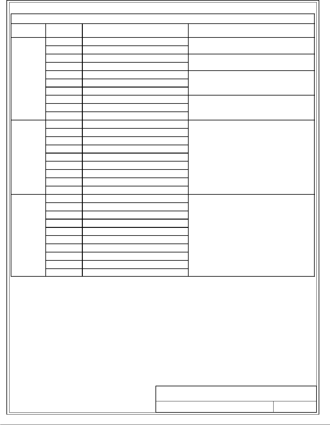
Table J. Customer Interface Panel Inputs and Outputs (Cont’d)
Terminal
Block
TB Pin # Name Description
1 ON UPS
Contacts used to in dicate On UPS status o
f
2 ON UPS RTN
C
o
n
t
a
c
t
s
u
s
e
d
t
o
i
n
d
i
c
a
t
e
O
n
U
P
S
s
t
a
t
u
s
o
f
Parallel Capacity/Redundant System
3 ON BYPASS
Contacts used to indicate On B
y
p
ass status o
f
4 ON BYPASS RTN
C
o
n
t
a
c
t
s
u
s
e
d
t
o
i
n
d
i
c
a
t
e
O
n
B
y
p
a
s
s
s
t
a
t
u
s
o
f
Parallel Capacity/Redundant System (See Note 6)
T
B
4
5 RELAY # 1 NC
G
l
N
O
d
N
C
l
T
B
4
6 RELAY # 1 NO
General purpose NO and NC relay
c
o
n
t
a
c
t
s
(
S
e
e
N
o
t
e
4
)
7 RELAY # 1 RTN
con
t
ac
t
s.
(
S
ee
N
o
t
e
4
)
8 RELAY # 2 NC
G
l
N
O
d
N
C
l
9 RELAY # 2 NO
General purpose NO and NC relay
c
o
n
t
a
c
t
s
(
S
e
e
N
o
t
e
5
)
10 RELAY # 2 RTN
con
t
ac
t
s.
(
S
ee
N
o
t
e
5
)
1 Bypass ∅ A
2 Bypass ∅ B
3 Bypass ∅ C
S
y
n
c
R
e
f
e
r
e
n
c
e
V
o
l
t
a
g
e
f
o
r
O
p
t
i
o
n
a
l
P
o
w
e
r
w
a
r
e
4 Sync Reference ∅A
S
ync
R
e
f
erence
V
o
l
tage
f
or
O
pt
i
ona
l
P
owerware
9315 S
y
nc Control Connect ions.
TB6
5 Sync Reference ∅B
9
3
1
5
S
y
n
c
C
o
n
t
r
o
l
C
o
n
n
e
c
t
i
o
n
s
.
A
l
d
f
O
i
l
P
H
T
i
C
l
6 Sync Reference ∅C
Also used for Optional Powerware Hot-Tie Control
a
n
d
H
o
t
T
i
e
w
i
t
h
S
y
n
c
C
o
n
t
r
o
l
c
o
n
n
e
c
t
i
o
n
s
7 Output ∅A
an
d
H
ot-
T
i
ew
i
t
h
S
ync
C
ontro
l
connect
i
ons.
8 Output ∅ B
9 Output ∅C
1 +12VDC
2 +12VDC RTN
3 +12VDC
4 +12VDC RTN
T
B
7
5 +12VDC
Optional CAN Power Supply Panel (A13) Terminal
B
l
o
c
k
f
o
r
P
o
w
e
r
w
a
r
e
9
3
1
5
(
5
0
0
k
V
A
7
5
0
k
V
A
)
T
B
7
6 +12VDC RTN
Block
f
or Po werware 9315 (500 k
V
A
--- 750 k
V
A
)
M
o
d
e
l
s
o
n
l
y
7 +12VDC
M
o
d
e
l
s
o
n
l
y
8 +12VDC RTN
9 +12VDC
10 +12VDC RTN
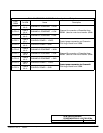
NOTES:
5. Relay 1 is normally deenergized and is only energized for an alarm condition.
6. Relay 2 is normally energized and is only deenergized for an alarm condition.
7. If the SSBM is setup for a Powerware Sync Control, the ON BYPASS contact is used for Sync
Control and is not available for customer use.