


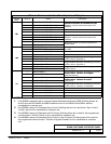

DESCRIPTION:
DRAWING NO: SHEET:
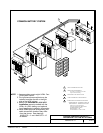
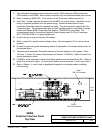
SSB M CUSTOMER INTERFACE PANEL
1of6
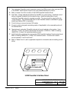
Customer Interface Panel
164201373---4
SSBM
To p Vi e w
A --- 13
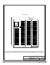
Powerware 9315 Parallel Capacity/Redundant System with PHP SSBM
164201373 Rev. A 092402
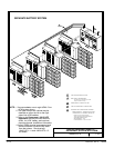
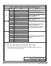
1. Two redundant PowerNet control networks connect UPM module to UPM module and
UPM module to the SSBM. Each network requires only one shielded twisted pair of wires.
2. Refer to drawing 164201373---13 for location of the Customer Interface panel (A1).
3. Use Class 1 wiring methods (as defined by t he NEC) for control wiring. Install the control
wiring in separate conduits from the power wiring. Install the twisted pair of each
redundant PowerNet network in separate conduits. The wire should be rated at 24 volts,
1 amp mi nimum. The recommended wire for the PowerNet network is shielded 20 g auge
twisted pair Belden 8762 (Powerware Part Number 175090703) or equivalent. The
recommended wire for the optional Network Power Supply panel (A13) for Powerware
9315---625/750 UPMs is 14 gauge twisted pair.
4. Control wiring run may not exceed 100 meters.
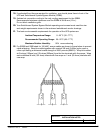
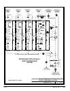
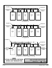
5. Refer to sheet 2 for typical control wiring ro uting. Use Arrangement C for a more robust
network.
6. Connect co ntrol wiring and terminating resistor (if applicable ) to the removable portion of
the terminal block.
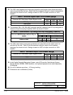
7. Terminate each redundant PowerNet network at the end modules in the system. Use a
120 ohm, 1/4 watt, 5% resistor (Powerware Part Number 141202041). Refer to sheet 2 f or
typical termination points.
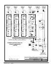
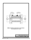
8. If SS BM is to be terminated, install terminating resistors onto terminal block TB1. Refer to
sheet 3 for terminal location. Connect each resistor across terminals 1 and 2 and 6 and 7.
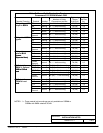
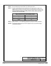
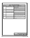
9. Refer to Tables I, J, and K, and to applicable chapters for information about installing
control wiring.
SSBM
Front
of
Port 2
DB --- 25 Connector
Port 1
DB --- 9 Connector