


5-- 1
Powerware 9315 Parallel Capacity/Redundant System with PHP SSBM
164201373 Rev. A 092402
Installing a Relay
Interface Module
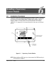
5.1 Installation Procedures
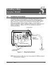
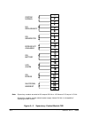
The optional Relay Interface Module (RIM) uses relay contact closures to indicate
the operating status and alarm condition of the Parallel Capacity/Redundant
system. The module uses an RS422 serial interface line and may support up to
eight critical loads. A maximum of two monitoring accessories (RMPs, RIMs, or
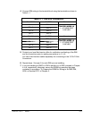
SCMs) can be installed. Refer to Chapter 4, Table 4---1 for the number of
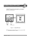
accessories permit ted. Figure 5---1 shows t he RIM wit h its four 15-pin connectors
labeled J1 through J4. Drawing 164201373---9 in Appendix A o utlines the
enclosure dimensions.
FL USH MOUNT
SURFACE
MOUNT
CONTINUES
Relay Interface Module
FOR HANGING
AT UPS
15-PIN D-SUB
CONNECTORS
J1 J2 J3 J4
Figure 5---1. Relay Interface Module
NOTE: Before installing an RIM, be sure you have prepared the SSBM according to
the instructions in Chapter 2.
5