


3 – QCP2340/2342
Installation and Removal
3-2 CF2351102-00 F
Q
3.1.1
LEDs
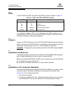
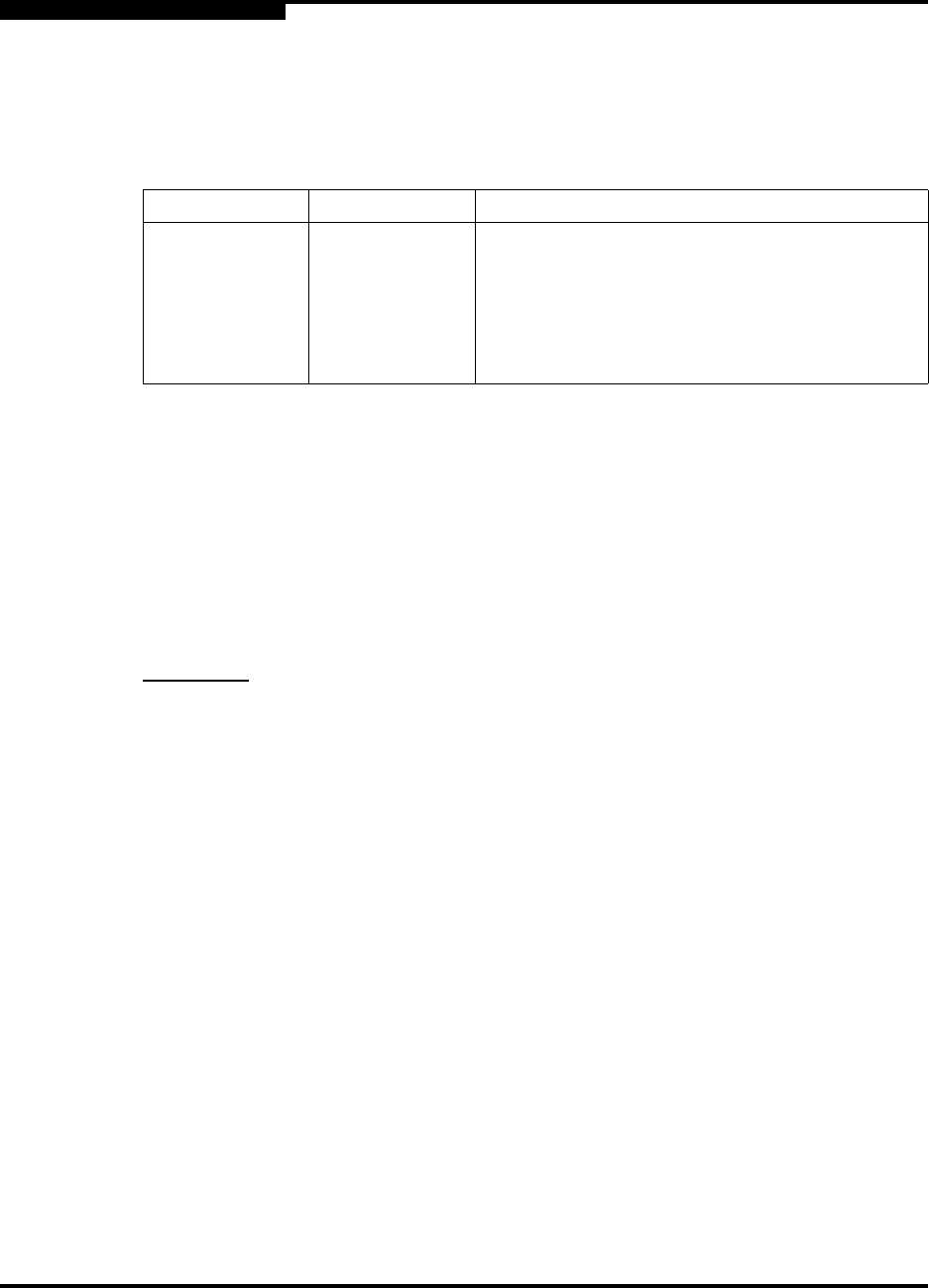
The QCP2340/2342 LED1 and LED2 (QCP2342) function as shown in table 3-1.
In a standard installation, LED3 is off, indicating that the HBA is active. In a hot
swap installation, LED3 turns blue while the HBA is inserted. If the LED turns off,
the HBA is inserted and has been configured.
3.1.2
Jumpers
Jumpers J4 (QCP2342) and J5 on the QCP2340/2322 HBA determine the default
state of connectors J2 (QCP2342) and J1, respectively. The jumpers are set at the
factory with a jumper plug on pins 2–3, which enables the connectors.
CAUTION!
Changing the jumper settings can result in the HBA being inoperable.
3.2
Installation and Removal
The following sections describe how to install the QCP2340/2342 HBA (standard
and hot swap installations) as well as how to remove the HBA.
Before you install the QCP2340/2342 HBA in your computer, you need the following:
■ A screwdriver (usually a Phillips #1)
■ An optical, multimode cable with an LC-style duplex connector
3.2.1
Installation in the Computer (Standard)
Perform the following steps to install the QCP2340/2342 HBA in your system. These
instructions are for a standard installation (the computer is shut down). See
section 3.2.2 for hot swap instructions.
1. Shut down the system.
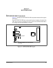
2. Choose any available cPCI slot. (Check the indicator lights next to (or above)
the available slots. The top two lights are off; the bottom light is amber.)
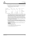
Table 3-1. LED1 and LED2 (QCP2342) Activity
Green LED Amber LED Activity
On On Power
On Off Online
Off On Signal acquired
Off Flashing Loss of synchronization
Flashing Flashing Firmware error