


4 – QSB2340/2342
Installation in the Computer
4-2 CF2351102-00 F
Q
4.1.1
LEDs
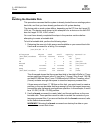
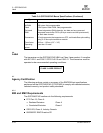
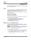
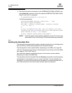
The QSB2340/2342 LED1 and LED2 (QSB2342) function as shown in table 4-1.
4.1.2
Jumpers
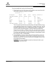
Jumpers J7 (QSB2342) and J8 on the QSB2340/2342 HBA determine the default
state of connectors J10 (QSB2342) and J9, respectively. The jumpers are set at the
factory with a jumper plug on pins 2–3, which enables the connectors.
CAUTION!
Changing the jumper settings can result in the HBA being inoperable.
4.2
Installation in the Computer
Before you install the QSB2340/2342 HBA in your computer, you need the following:
■ A screwdriver (usually a Phillips #1)
■ An optical, multimode cable with an LC-style duplex connector
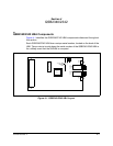
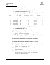
Perform the following steps to install the QSB2340/2342 HBA in your system:
1. Shut down the computer.
2. Remove the computer cover and save the screws.
3. Choose any available SBus slot.
4. Remove the slot cover.
5. Place the QSB2340/2342 HBA into the slot. Carefully press the HBA into the
slot until it seats firmly.
6. Connect the appropriate cable from the devices to the J1 and J2 connectors.
7. Carefully reinstall the computer cover. Insert and tighten the computer cover
screws.
8. Power up all external FC devices, then power up the system and observe the
monitor.
NOTE: SunSPARC systems do not display the BIOS banner.
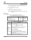
Table 4-1. LED1 and LED2 (QCP2342) Activity
Green LED Amber LED Activity
On On Power
On Off Online
Off On Signal acquired
Off Flashing Loss of synchronization
Flashing Flashing Firmware error