3 – QCP2340/2342
Installation and Removal
3-4 CF2351102-00 F
Q
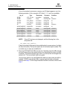
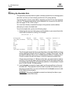
A list of the system’s processors, memory, and I/O boats appears, as in the
following example. In this example, cPCI slots 0, 1, 3, and 4 are available.
NOTE: If the cPCI slots are not displayed, add the following line to the
etc/system file:
set sghsc:cpci_enable=1
Check the indicator lights next to the available slots (in some systems, the lights
are above the slots). The top two lights are off; the bottom light is amber. This
is another way to verify an available slot.
3. Place the QCP2340/2342 HBA into the slot. Carefully press the HBA into the
slot until it seats firmly (the switch clicks into a locked position when the HBA
is seated). The bottom indicator light next to (or above) the slot changes from
amber to off. The top indicator light turns green.
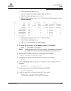
The hot swap LED3 on the QCP2340/2342 HBA turns blue while the HBA is
inserted. If LED3 turns off, the HBA is inserted and has been configured;
continue with step 6. If LED3 stays blue after the HBA is inserted, continue with
step 4.
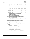
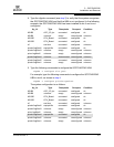
Ap_Id Type Receptacle Occupant Condition
N0.IB6 cPCI_I/O_bo connected configured ok
N0.IB8 unknown empty unconfigured unknown
N0.SB0 CPU_Board connected configured ok
N0.SB2 CPU_Board connected configured ok
c0 scsi-bus connected configured unknown
pcisch0:sg6slot2 stpcipci/fhs connected configured ok
pcisch0:sg6slot3 unknown empty unconfigured unknown
pcisc1:sg6slot0 unknown empty unconfigured unknown
pcisch2:sg6slot4 unknown empty unconfigured unknown
pcisch2:sg6slot5 unknown connected unconfigured unknown
pcisch3:sg6slot1 unknown empty unconfigured unknown


