


M30850T2-EPB User’s Manual 2. Setup
REJ10J1005-0200 Rev.2.00 April 1, 2007
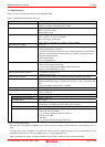
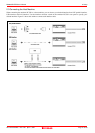
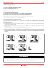
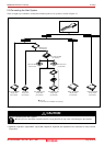
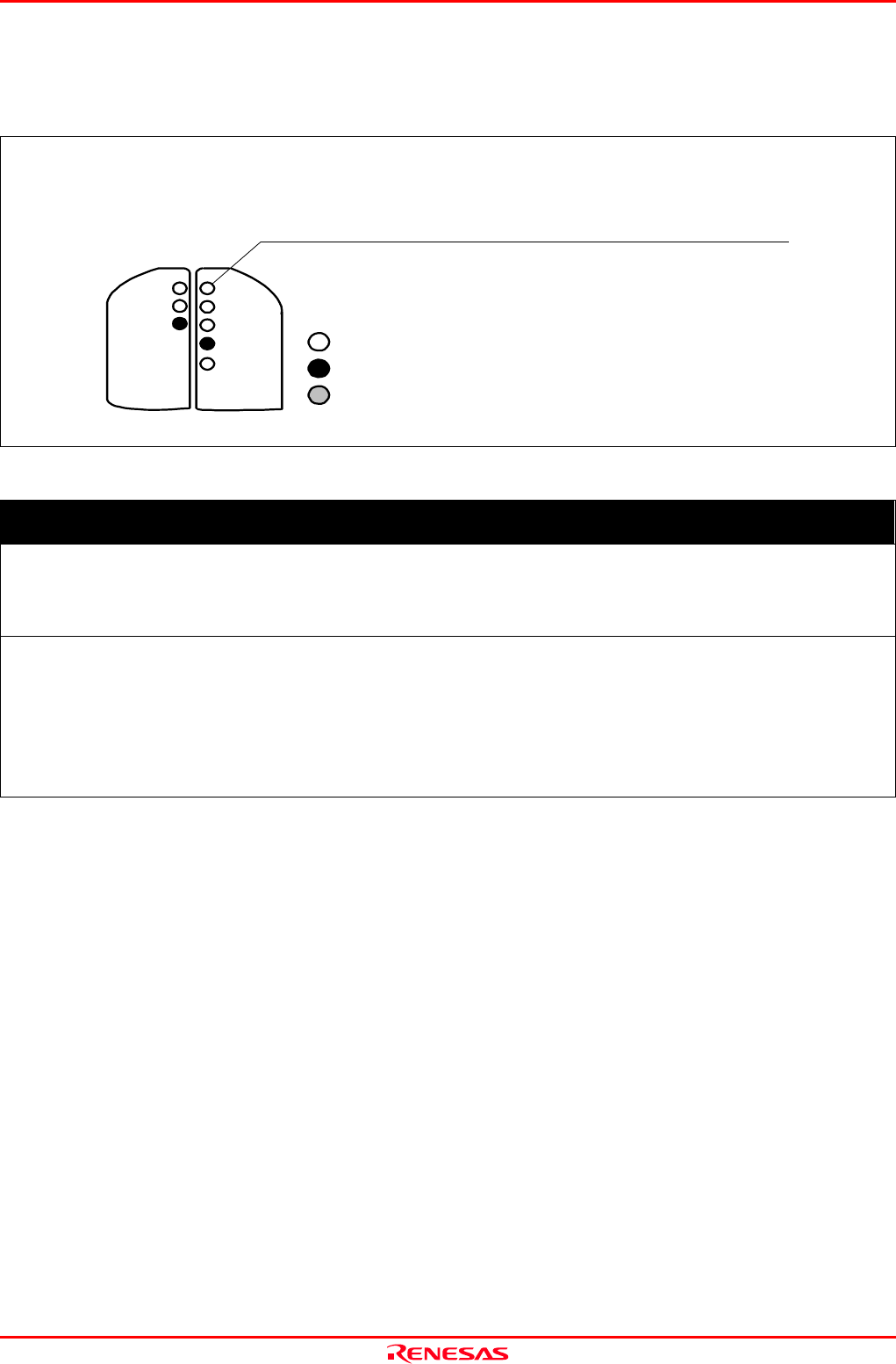
2.6.4 LED Display When the Emulator Starts Up Normally
Figure 2.4 shows upper panel LED lighting status when the emulator started up properly. Check it when starting up the
emulator system.
- If this LED does not light, check the power supply voltage
of the user system.
- Check to make sure that power is supplied to all the power pins.
- When the user system is not connected, this LED does not light.
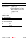
POWER
POWER
SAFE
ERROR
CLOCK
RESET
RUN
WARNING
TARGET
STATUS
SYSTEM
STATUS
,
: ON
: OFF
: Flashing
Figure 2.4 LED display when the power turned on PC7501
IMPORTANT
Note on Memory Expansion and Microprocessor Modes:
z To use memory expansion or microprocessor mode, be sure to set pins RDY#, HOLD# and NMI# so that they
are not active at start-up. Otherwise the emulator system will not start up correctly.
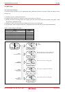
Note on CLOCK LED:
z If CLOCK LED does not turn on, check the following:
(1) Immediately after starting PC7501 (before starting the emulator debugger)
Check if the oscillation circuit within the PC7501 emulator main unit oscillates normally.
(2) After starting the emulator debugger (after setting the Init dialog box)
Check the oscillation circuit set in the Init dialog box oscillates normally.
Page 25 of 98