


M30850T2-EPB User’s Manual 2. Setup
REJ10J1005-0200 Rev.2.00 April 1, 2007
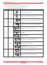
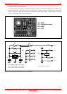
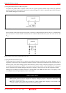
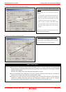
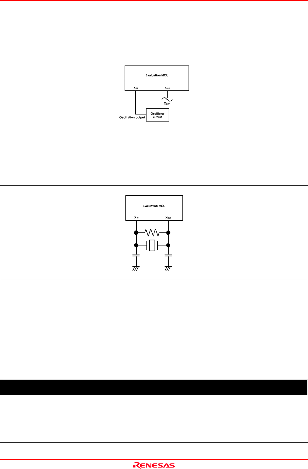
(2) Using the Oscillator Circuit on the User System
To operate this product with an oscillator circuit of the user system, input the oscillator output at 50% duty (within the
operating range of the evaluation MCU) into pin X
IN
as shown in Figure 2.21. Pin X
OUT
should be open. Choose "External"
in the emulator debugger to use this clock.
Figure 2.19 External oscillator circuit
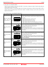
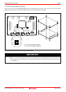
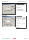
In the oscillator circuit shown in Figure 2.22 where a resonator is connected between pins X
IN
and X
OUT
, oscillation does
not occur because a converter board is used between the evaluation MCU and the user system. It is same for X
CIN
and
X
COUT
.
Figure 2.20 Circuit in which oscillation does not occur
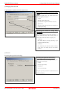
(3) Using the Internal Oscillator Circuit
The dedicated circuit in the PC7501 can generate any arbitrary frequency specified by the emulator debugger, and it is
supplied as a main clock. It does not depend on either the oscillator circuit board in the PC7501 or the oscillator circuit on
the user system. If you want to debug programs without the user system or change a frequency temporarily, you can check
its operation before preparing an oscillator. If you want to use the internal oscillator circuit of the PC7501 as a main clock,
choose "Generated" in the emulator debugger and specify a frequency you like to use for this clock supplied to an MCU.
Although you can change a frequency between 1.0 and 99.9 MHz by 0.1 MHz for the PC7501, do not specify a value
exceeding the maximum input frequency of the X
IN
of the MCU.
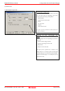
IMPORTANT
Notes on Internal Oscillator Circuit:
z The internal generator circuit is equipped for temporary debugging purposes. Temperature characteristics of
frequencies are not guaranteed.
z Be sure to evaluate your system with an oscillator or oscillator module whose frequency is same as that of the
internal oscillator circuit (internal clock) for final evaluation purposes.
Page 44 of 98