


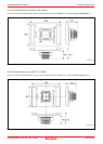


M30850T2-EPB User’s Manual 4. Hardware Specifications
REJ10J1005-0200 Rev.2.00 April 1, 2007
IMPORTANT
Notes on Reset Vector Area:
z For a reset vector area, memory of the emulator is always selected regardless of the setting of the EMEM dialog
box. Therefore when setting a microprocessor mode, to use a ROM of the user system etc. as an area including
a reset vector area, set a reset vector using a dump window etc.
z A reset vector area can be changed only when a program is stopped.
Notes on Stack Area:
z With this product, a maximum 20 bytes of the user stack is consumed as a work area. Therefore, ensure the +20
byte maximum capacity used by the user program as the user stack area. If the user stack does not have enough
area, do not use areas which cannot be used as stack (SFR area, RAM area which stores data, or ROM area) as
work area. Using areas like this is a cause of user program crashes and destabilized emulator control.
z With this product, the interrupt stack pointer (ISP) is set to 00500h and used as stack area after the reset is
released.
Notes on Maskable Interrupts:
z Even if a user program is not being executed (including when run-time debugging is being performed), the
evaluation MCU keeps running so as to control the emulator, so the function such as timer is operated. Take
note that when the user program is not being executed (including when run-time debugging is being performed),
a peripheral I/O interruption is not accepted.
Notes on Access Prohibited Area:
z The emulator control register (000020h--00003Fh) in the SFR is read- and write-protected. When this register is
accessed, emulator control cannot be utilized.
z With this product, address FFFFFFh cannot be read or written in correctly.
Note on DMA Transfer:
z With this product, the user program is stopped with a loop program to a specific address. Therefore, if a DMA
request is generated by a timer or other source while the user program is stopped, DMA transfer is executed.
However, make note of the fact that DMA transfer while the program is stopped may not be performed
correctly. Also note that the below registers have been changed to generate DMA transfer as explained here
even when the user program is stopped.
(1) DMA0 transfer count register DCT0
(2) DMA1 transfer count register DCT1
(3) DMA0 memory address register DMA0
(4) DMA1 memory address register DMA1
(5) DMA2 transfer count register DCT2 (R0)
(6) DMA3 transfer count register DCT3 (R1)
(7) DMA2 memory address register DMA2 (A0)
(8) DMA3 memory address register DMA3 (A1)
Note on DMAC II Transfer Completion Interrupts:
z You can use DMAC II transfer completion interrupts during program execution only. Do not generate DMAC II
transfer completion interrupts when you use any function but program execution.
Note on Final Evaluation:
z Be sure to evaluate your system with an evaluation MCU. Before starting mask production, evaluate your
system and make final confirmation with a CS (Commercial Sample) version MCU.
Page 78 of 98