


M30850T2-EPB User’s Manual 2. Setup
REJ10J1005-0200 Rev.2.00 April 1, 2007
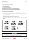
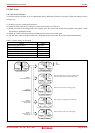
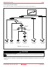
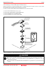
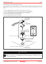
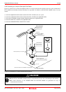
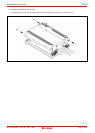
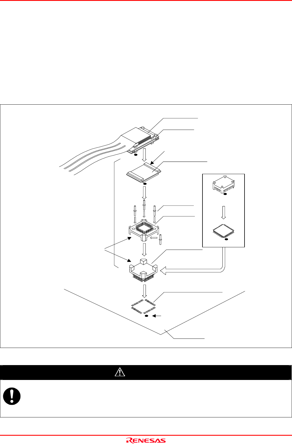
2.9.6 Connecting to a 144-pin 0.5mm pitch Foot Pattern
Figure 2.13 shows how to connect the emulation probe to a 144-pin 0.5mm pitch foot pattern on the user system with the M3T-
FLX-144NSD (not included), and here following is its procedure. For details on the M3T-FLX-144NSD, refer to its user's
manual.
(1) Attach the NQPACK144SD included with the M3T-FLX-144NSD to the user system.
(2) Attach the YQPACK144SD included with the M3T-FLX-144NSD to the NQPACK144SD.
(3) Insert the YQ-GUIDEs included with the YQPACK144SD to the YQPACK144SD.
(4) Attach the M3T-FLX-144NSD to the YQPACK144SD.
(5) Attach the M30850T2-EPB to the M3T-FLX-144SD.
*
M3T-FLX160-EPB
M30850T2-EPB
CN2 side
(5)
(1)
144-pin 0.5mm pitch
(PLQP0144KA-A) foot pattern
No.1 pin
User system
M3T-FLX-144NSD
(not included)
FLASH MCU etc.
On-board evaluation
*: These four items are available in one package.
YQPACK144SD
NQPACK144SD(-ND)
HQPACK144SD
(not included)
(2)
(3)
(4)
YQ-GUIDE(x4)
These corners are not round.
Figure 2.13 Connecting to a 144-pin 0.5mm pitch foot pattern
CAUTION
Notes on Connecting the User System:
z Take care not to attach the converter board in a wrong direction. It may cause a fatal damage to the emulator.
z The small connectors of the M30850T2-EPB and M3T-FLX-144NSD are guaranteed for only 50
insertion/removal iterations.
Page 35 of 98