


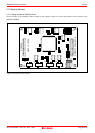

M30850T2-EPB User’s Manual 2. Setup
REJ10J1005-0200 Rev.2.00 April 1, 2007
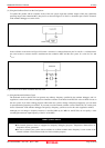
2.10.2 Selecting Clock Supply
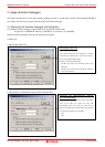
You can choose a clock supplied to the evaluation MCU by the Emulator tab in the Init dialog box of the emulator debugger.
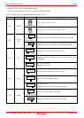
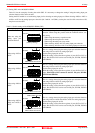
Table 2.4 lists the factory-settings of each clock supply.
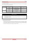
Table 2.4 Clock supply to the MCU and default settings
Clock Display of emulator debugger Description Default setting
Internal
Internal oscillator circuit
(OSC-3 or OSC-2)
Yes
External Oscillator of user system -
Main X
IN
-X
OUT
Generated
Internal generator circuit
(1.0 to 32.0 MHz)
-
Internal
Internal oscillator circuit
(32.768 kHz)
-
Sub X
CIN
-X
COUT
External Oscillator of user system Yes
IMPORTANT
Notes on Changing the Clock Supply:
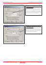
z The clock supply can be set by the Init dialog box when starting up the emulator debugger or inputting CLK
command on the script window.
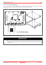
z For XCIN-XCOUT, it is necessary to set switches in the emulator. For details, refer to "2.10.1 Setting Switches
of Emulation Probe" (page 38).
(1) Using an Internal Oscillator Circuit Board
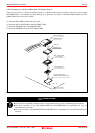
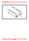
1) Kinds of Oscillator Circuit Boards
The PC7501 comes with an oscillator circuit board OSC-3 (30 MHz). And an oscillator circuit board OSC-3 (32 MHz)
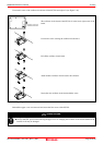
and an oscillator circuit board OSC-2 (bare board) are included with this product. If you use the internal oscillator
circuit board OSC-3 (32 MHz) or OSC-2 of the PC7501 as a main clock, choose "Internal" in the emulator debugger
after replacing oscillator circuit boards to change a clock supplied to an MCU.
Page 40 of 98