


M34571T2-CPE User’s Manual 2. Setup
REJ10J0972-0100 Rev.1.00 February 10, 2006 Page 20 of 72
2. Setup
This chapter describes the preparation for using this product, the procedure for starting up the emulator and how to change
settings.
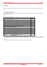
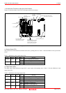
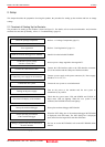
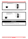
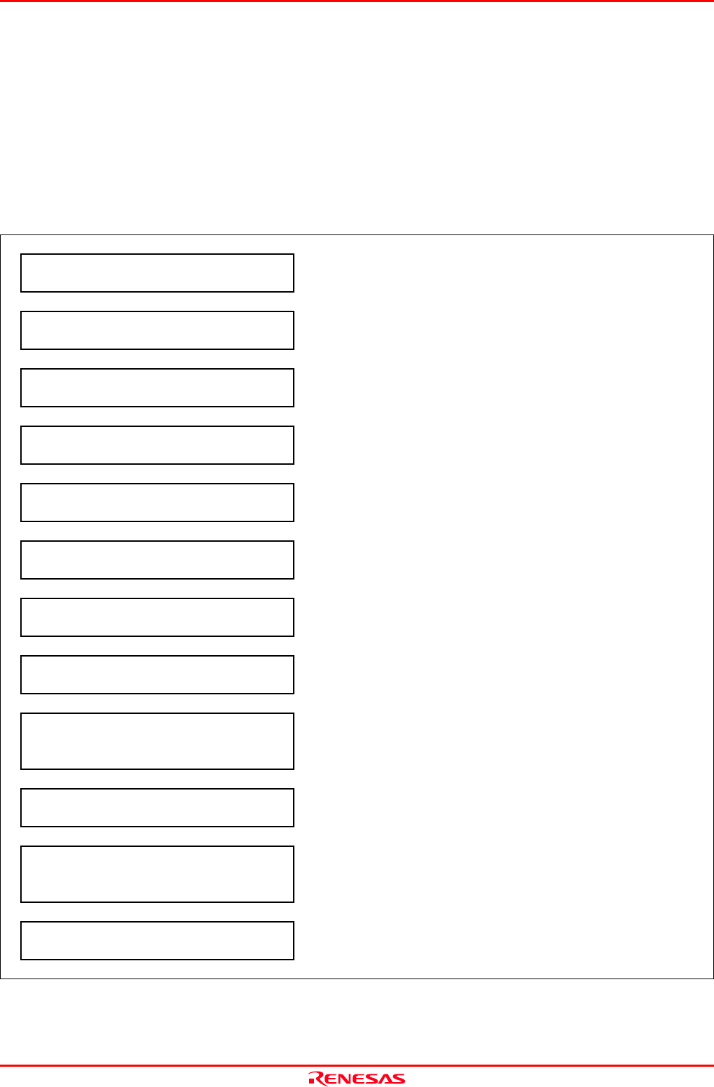
2.1 Flowchart of Starting Up the Emulator
The procedure for starting up the emulator is shown in Figure 2.1. For details, refer to each section hereafter. And, when the
emulator does not start up normally, refer to “5. Troubleshooting” (page 65).
Check the package components. Refer to “1.1 Package Components (page 13).
↓
User registration Refer to “User Registration” (page 11).
↓
Install the emulator debugger M3T-PD45M. Install it from the included CD-ROM.
↓
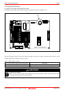
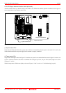
Set the MCU power voltage
selection switch (SW1).
Select a power voltage supplied to the target MCU.
↓
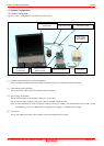
Connect the USB interface cable.
Connect the USB interface cable to the USB interface connector
(J2) of the emulator and the USB port of the host machine.
↓
Connect the power supply for the emulator.
Connect a power supply to the power connector (J1). Power supply
should be 5.0 V ±5%, 2 A.
↓
Connect the user system. Connect the user system as occasion demands.
↓
Turning on the power supply.
Turn on the power to the emulator and the user system as
simultaneously as possible.
↓
Check the LED display of the emulator.
Check that the system status LED, and POWER and CLOCK of
target status LED are lighting. When the user system is not
connected, the POWER LED does not light up.
↓
Start up the emulator debugger. Start up the emulator debugger M3T-PD45M.
↓
Set the operating environment
of the emulator debugger.
When the INIT dialog box of the emulator debugger M3T-PD45M
is displayed, click OK button. The INIT dialog box is displayed
again, then select the target MCU and click OK button.
↓
Debug a program with various functions of
the M3T-PD45M.
For how to use the M3T-PD45M, refer to the M3T-PD45M online
manual.
Figure 2.1 Flowchart of starting up the emulator