


M34571T2-CPE User’s Manual 2. Setup
REJ10J0972-0100 Rev.1.00 February 10, 2006
Page 33 of 72
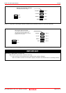
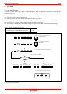
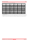
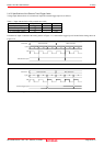
Table 2.5 Connector assignments of the 26-wire normal-pitch cable
Connector pin
No.
MCU pin No. Signal
Connector pin
No.
MCU pin No. Signal
1 1 VDD 26 24 C/CNTR1
2 2 VSS 25 23 D4/CNTR0
3 3 XIN 24 22 D3
4 4 XOUT 23 21 D2
5 5 K 22 20 D1
6 6 RESET# 21 19 D0
7 7 P00 20 18 P31
8 8 P01 19 17 P30
9 9 P02 18 16 P21/INT1
10 10 P03 17 15 P20/INT0
11 11 P10 16 14 P13
12 12 P11 15 13 P12
13
-
VSS 14
-
VSS
* VDD is connected for the emulator system to monitor power supply of the target, and the emulator system does not supply
power to the user system
* XIN and XOUT are not connected. XIN is input from oscillator board OSC-2 to the MCU, and it is not input from an
oscillator circuit on the user system. To change a system clock frequency, change the circuit of the oscillator board OSC-2.