


M34571T2-CPE User’s Manual 4. Hardware Specifications
REJ10J0972-0100 Rev.1.00 February 10, 2006
Page 59 of 72
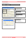
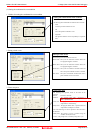
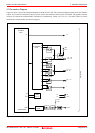
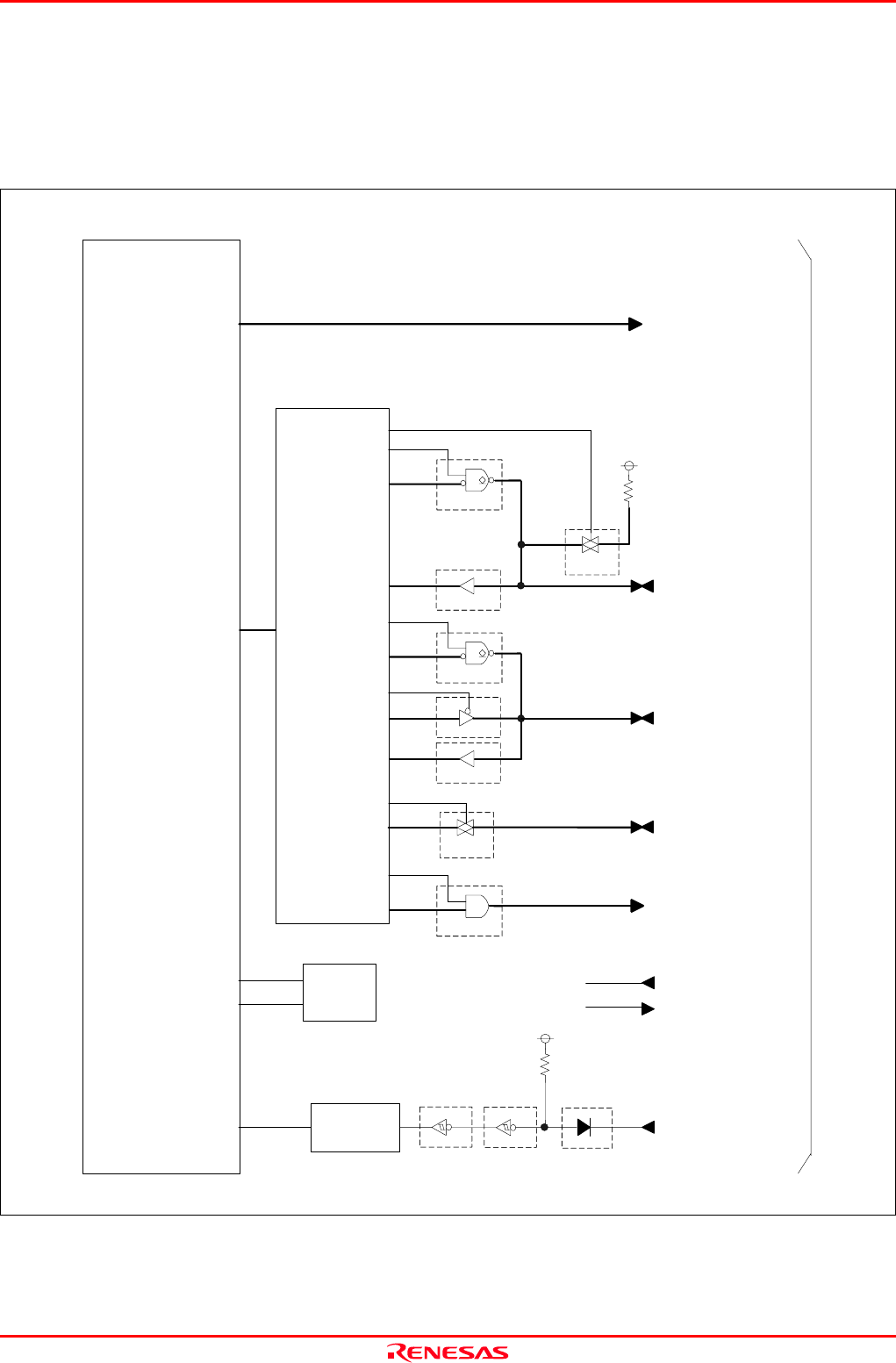
4.3 Connection Diagram
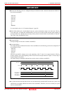
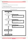
Figure 4.2 shows a part of the connection diagram of the M34571T2-CPE. This connection diagram mainly shows the interface
section. The circuits not connected to the user system such as the emulator's control system are omitted. The signals not shown
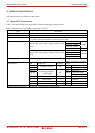
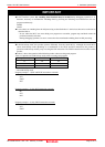
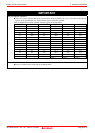
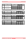
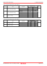
in Figure 4.2 connect the evaluation MCU and the user system directly. Tables 4.4, 4.5, 4.6, 4.7, 4.8 and 4.9 show IC electric
characteristics of this product for reference purposes.
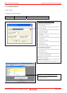
Figure 4.2 Connection diagram of the M34571T2-CPE
Evaluation
MCU
M34571G6FP
User system
Oscillator
circuit
(OSC-2)
XIN
XOUT
N.C
N.C
XIN
XOUT
RESETRESET
74VHC14
74VHC14
1SS355
*
RESET
circuit
VDD2
1MΩ
74HC126
74HC4050
74HC4066
Port emulation
circuit
P00 -- P03
P10 -- P13
VDD2
68kΩ
74ALS641A
74HC4050
P30 -- P31
D0 -- D3
74VHC08
74HC4066
P20 -- P21
K
D4
C
D4
74ALS641A