


M34571T2-CPE User’s Manual 2. Setup
REJ10J0972-0100 Rev.1.00 February 10, 2006
Page 37 of 72
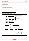
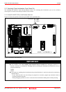
2.10 Connecting the External Trace/Trigger Cable
Using the external trace/trigger cable enables record/reference a hardware break by the external trigger, and changes of an
external signal level in the trace window
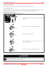
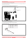
2.10.1 Connecting the External Trace/Trigger Cable to the Emulator System
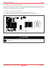
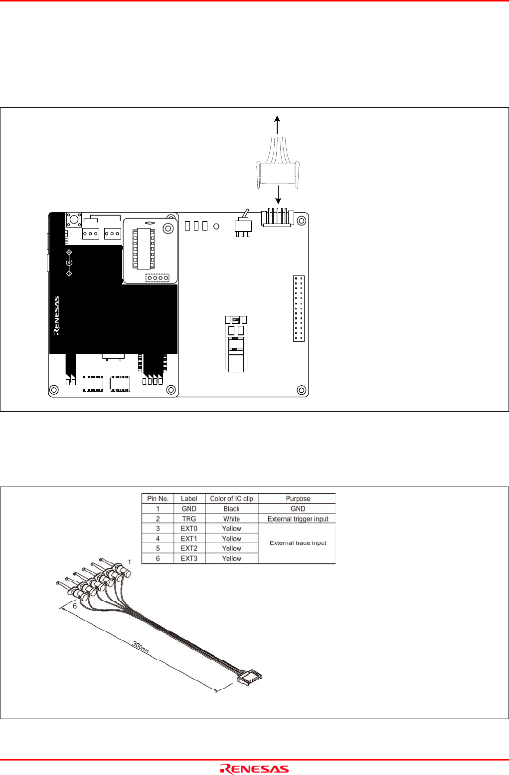
Connect the external trace/trigger cable to the connector J4 of the emulator
Figure 2.15 Connecting the external trace/trigger cable
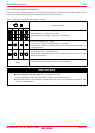
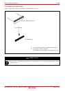
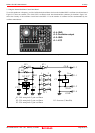
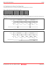
2.10.2 Connecting the External Trace/Trigger Cable to the User System
Connect the GND, TRG and EXT0 to EXT3 of the external trace cable to the user system. Figure 2.16 shows the pin
assignment of the external trace cable.
Figure 2.16 Pin assignment of the external trace cable
User system
Connect the external cable
to connector J4
M34571T2-CPEB REV.A
TP1
VDD2
GND
TP2
WRST
POF
LED1
POWER
SAFE
STATUS
J4
3V
5VSW1
J3
13
14
1
26
MADE
POWER
COMPACT EMULATOR
CLOCK
RESET
RUN
LED3
LED6
LED5LED4
POWER
SAFE
LED2
LED1
SAFE
POWER
POWER
CLOCK
RESET
RUN
M 34571T2-CPE
STATUS
SYSTEM
STATUS
TARGET
MADE IN JAPAN
COMPACT EMULATOR
POWER
5.0V
USB
I
NT
3.3V5.0V
JP1
JP2
EXT